Latching zip-mode actuated mono wafer MEMS switch

a mems switch and zip-mode technology, applied in the field of current generation of radio frequency mems switches, can solve the problems of many milliseconds of ringing upon opening, the safe operating margin of the device, and the inability to hot-switch radio frequency (rf) power is often limited

Inactive Publication Date: 2011-06-14
THE UNITED STATES OF AMERICA AS REPRESETNED BY THE SEC OF THE AIR FORCE
View PDF8 Cites 20 Cited by
  • Summary
  • Abstract
  • Description
  • Claims
  • Application Information

AI Technical Summary

Benefits of technology

[0018]It is another object of the invention to disclose a MEMS switch fabrication in which an ultra thin and flexible zip mode switch beam member can be protected from physical damage during switch fabrication.

Problems solved by technology

In a conventional spring-force restored MEMS switch, the ability to hot-switch radio frequency (RF) power is often limited by radio frequency (RF) latching of the device.
This temperature-induced variation in spring constant reduces the safe operating margins of the device because the device must be stiff enough to operate at high temperature, but not so stiff that the operating voltage is excessive at low temperature.
Unfortunately however, for most spring-force restored devices, their relatively high mechanical Q-factors result in many milliseconds of ringing upon opening when operating in even moderate vacuum.
In both of these instances however, the S-shaped actuator is formed through use of a double a wafer-bonding process rather than on a single wafer and the benefits of new self-latching switch operating mode disclosed herein appear to have been unrecognized.

Method used


Image

  • Latching zip-mode actuated mono wafer MEMS switch
  • Latching zip-mode actuated mono wafer MEMS switch
  • Latching zip-mode actuated mono wafer MEMS switch

Examples


Embodiment Construction

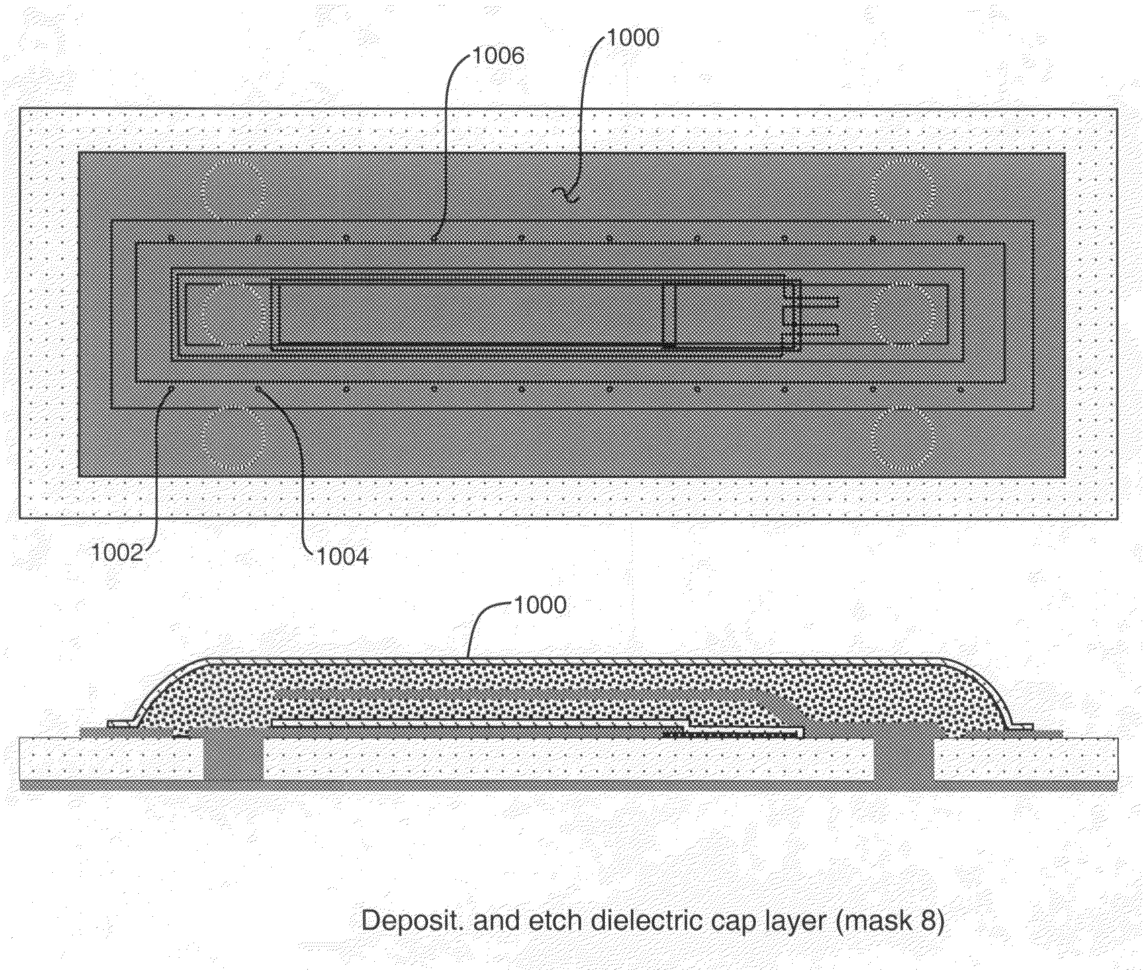
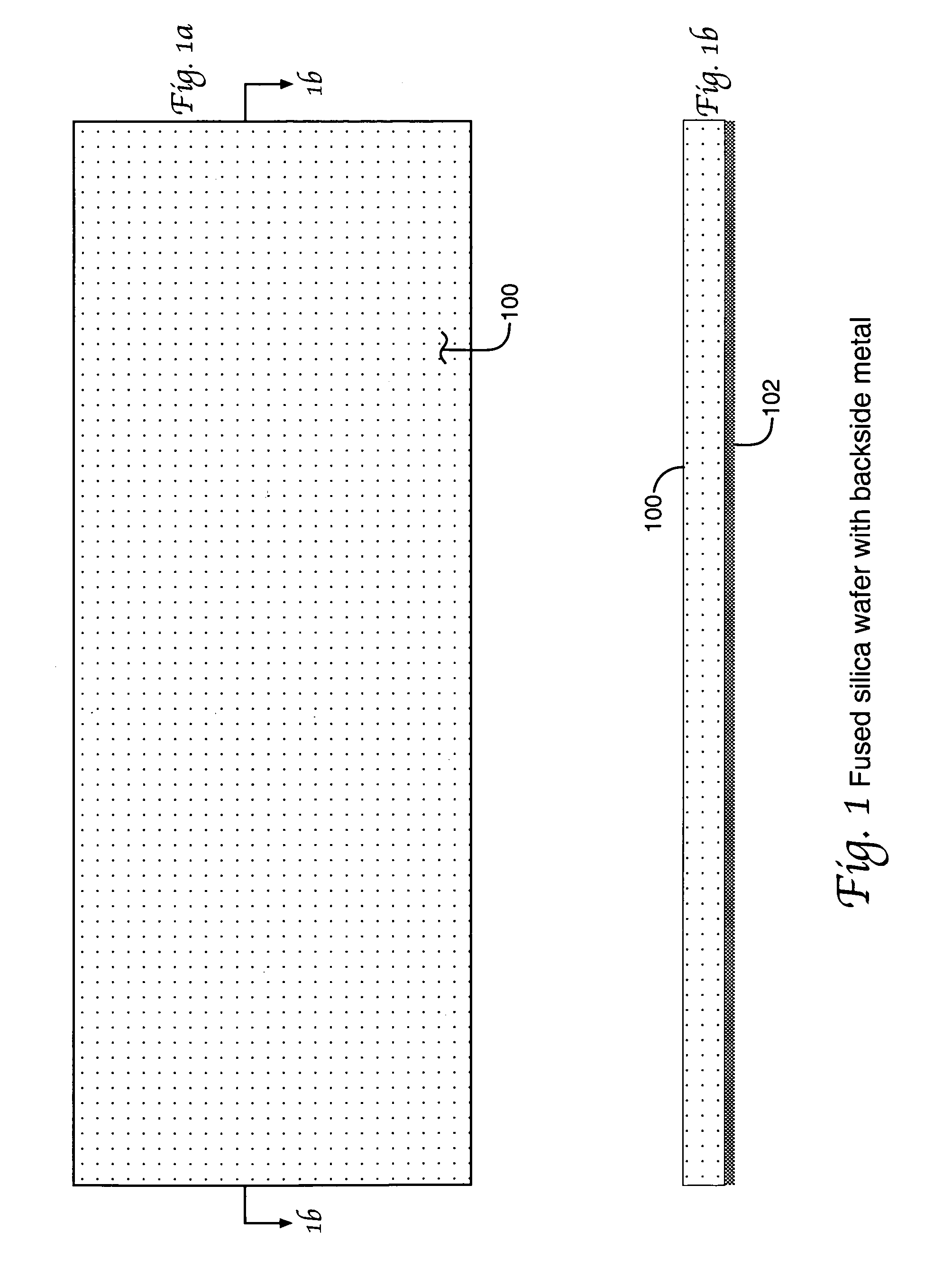
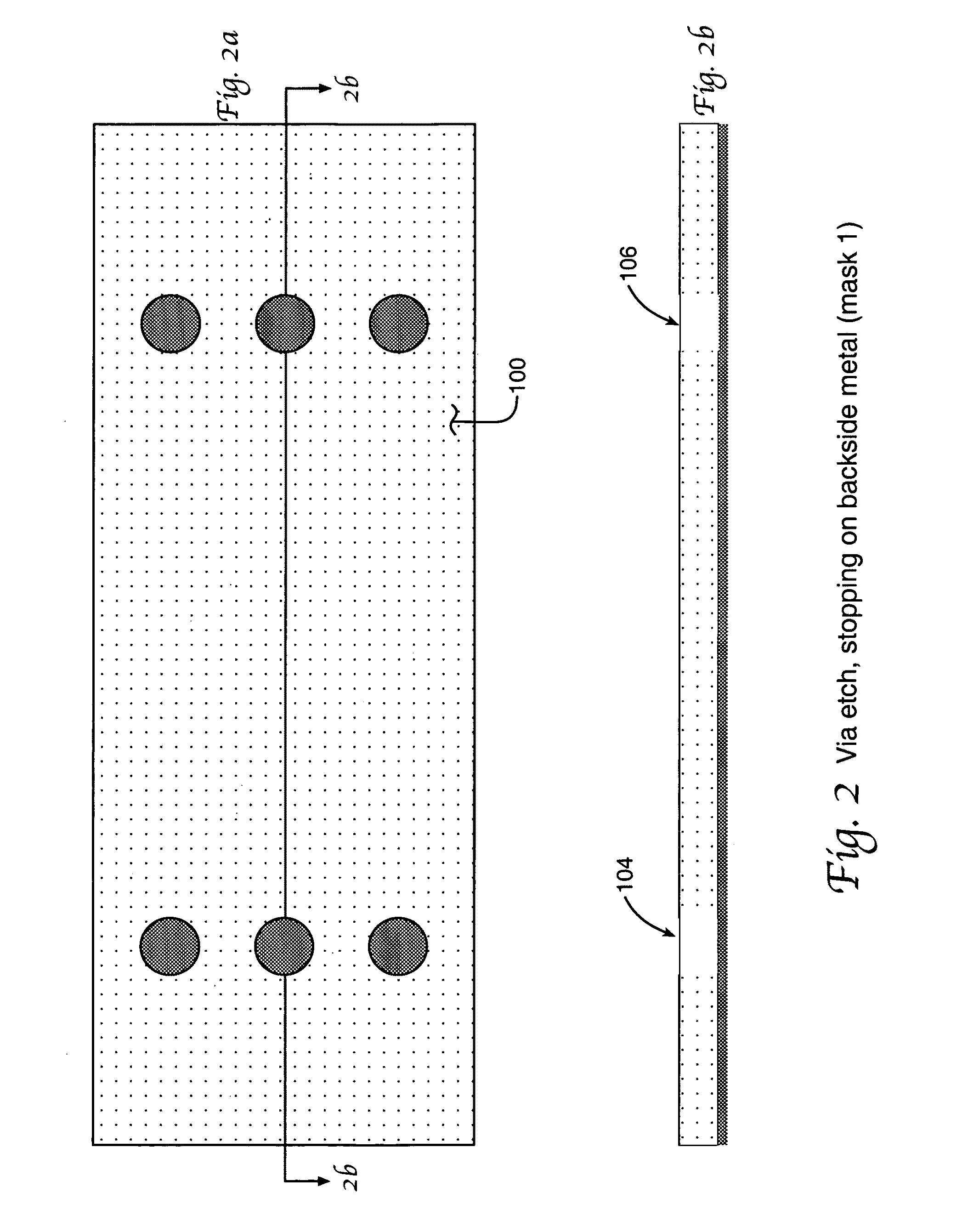
[0067]FIG. 1 through FIG. 14 in the drawings shows a sequence of integrated circuit compatible fabrication steps for a MEMS switching device according to the present invention. Subsequent drawings included herein show characteristics and alternate switch structural views for MEMS switches according to the invention. A notable aspect of the fabricated MEMS device is the single wafer achievement of a latching zip-mode actuated mems switch especially suited to capacitance coupled switching of radio frequency signals. The self latching capabilities of this switch are also of significant interest.

[0068]The FIG. 1-FIG. 14 devices may be fabricated on a single silica or sapphire substrate by a sequence of specific steps commencing with the backside metal 102 covered wafer 100 as is shown in the FIG. 1a and FIG. 1b drawings. The FIG. 1a and FIG. 1b drawings represent plan and profile views of the wafer 100 in a conventional manner as may be appreciated from the indicating line 108 and the r...


PUM


Abstract

A latching zip-mode actuated mono wafer MEMS switch especially suited to capacitance coupled signal switching of microwave radio frequency signals is disclosed. The single wafer fabrication process used for the switch employs sacrificial layers and liquid removal of these layers in order to also provide needed permanent physical protection for an ultra fragile switch moving arm member. Latched operation of the achieved MEMS switch without use of conventional holding electrodes or magnetic fields is also achieved. Fabrication of a single MEMS switch is disclosed however large or small arrays may be achieved.

Description

CROSS REFERENCE TO RELATED PATENT DOCUMENTS[0001]The present document is a Continuation In Part of the co-pending and commonly assigned patent application document “PROCESS INTEGRATED PACKAGING OF RADIO FREQUENCY (RF) MICROELECTROMECHANICAL SYSTEMS (MEMS) SWITCHES”, Ser. No. 10 / 901,315, filed 27 Jul. 2004 now U.S. Pat. No. 7,381,583 with claim of priority to a Provisional Application document of Ser. No. 60 / 573,892 dated May 24, 2004. The contents of these related application documents are hereby incorporated by reference herein.[0002]The present document is related to the co-pending, common filing date and commonly assigned U.S. Patent application “LATCHING ZIP-MODE ACTUATED MONO WAFER MEMS SWITCH METHOD” Ser. No. 12 / 152,130, filed of even date herewith. The contents of this related application document are also hereby incorporated by reference herein.[0003]Each of the 60 / 930,357 and Ser. No. 12 / 152,130 related documents is filed in the names of four inventors: John L. Ebel, Rebecc...

Claims


Application Information

Patent Timeline
Patent Type & Authority Patents(United States)
IPC IPC(8): H01L21/00
CPCB81C1/00333H01H59/0009B81B2201/018H01H2059/0045B81C2203/0154
Inventor EBEL, JOHN L.CORTEZ, REBECCALEEDY, KEVIN D.STRAWSER, RICHARD E.
Owner THE UNITED STATES OF AMERICA AS REPRESETNED BY THE SEC OF THE AIR FORCE
Why Eureka
Try Eureka