
Hybrid circuit with an integral antenna

a hybrid circuit and integral technology, applied in the structural form of radiating elements, resonant antennas, substantially flat resonant elements, etc., can solve the problems of antenna interference and integration of a full wireless system, and achieve the effect of preventing attenuation of the signal received and reducing nois

Active Publication Date: 2011-06-14
ORIGIN GPS LTD
View PDF37 Cites 20 Cited by
  • Summary
  • Abstract
  • Description
  • Claims
  • Application Information

AI Technical Summary

Benefits of technology

This configuration enhances signal quality, reduces the need for amplification, and simplifies device construction by integrating all functions, including the antenna, into a compact, lightweight package.

Problems solved by technology

One problem faced by manufacturers is integration of a full wireless system (e.g. Wi-Fi, Bluetooth, mobile telephone) into a single hybrid circuit package.
Additionally, the antenna is subject to interference, from the circuit and to low gain because of the circuit and the packaging.

Method used


Image

  • Hybrid circuit with an integral antenna
  • Hybrid circuit with an integral antenna
  • Hybrid circuit with an integral antenna

Examples


Embodiment Construction

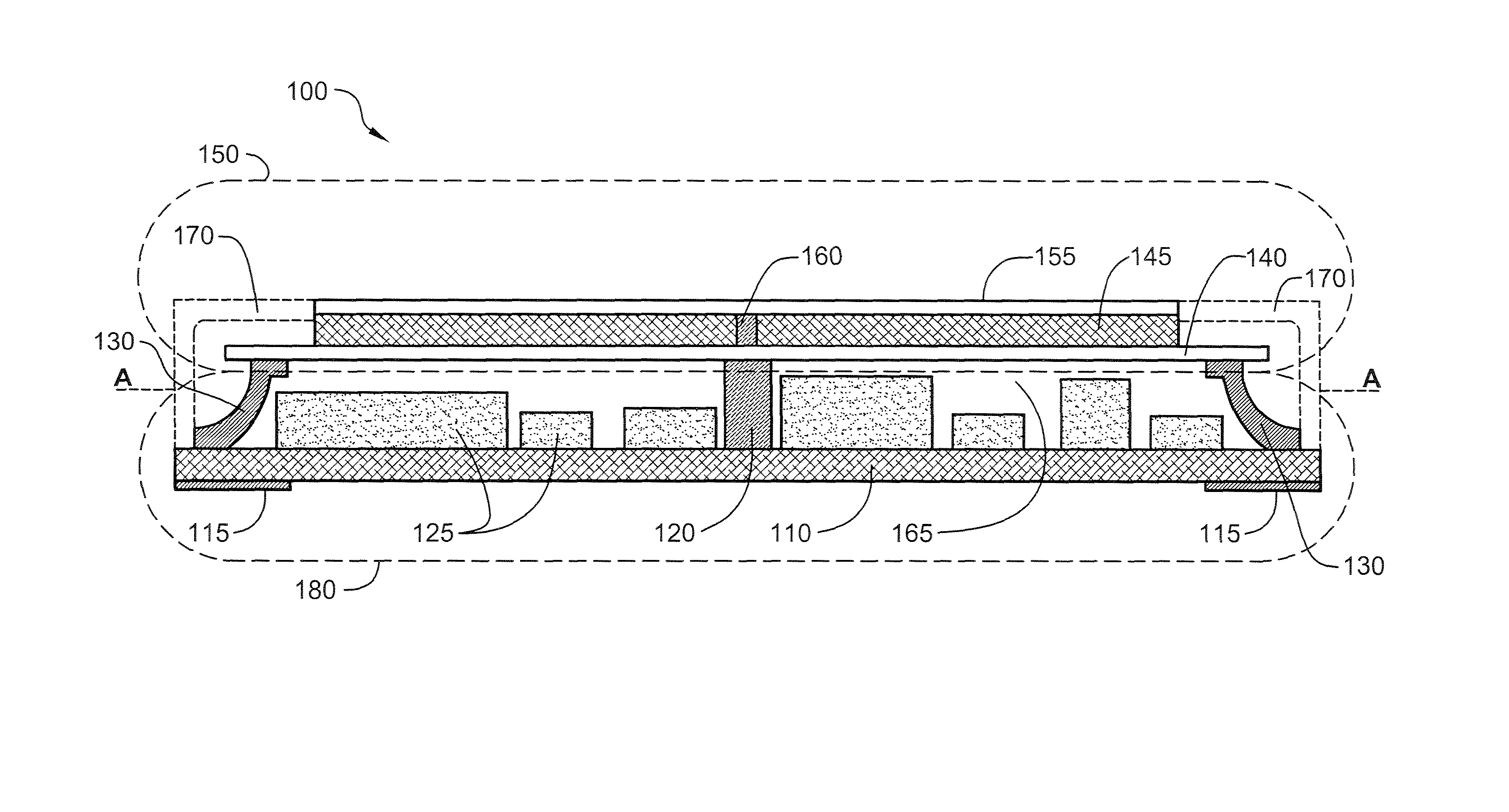
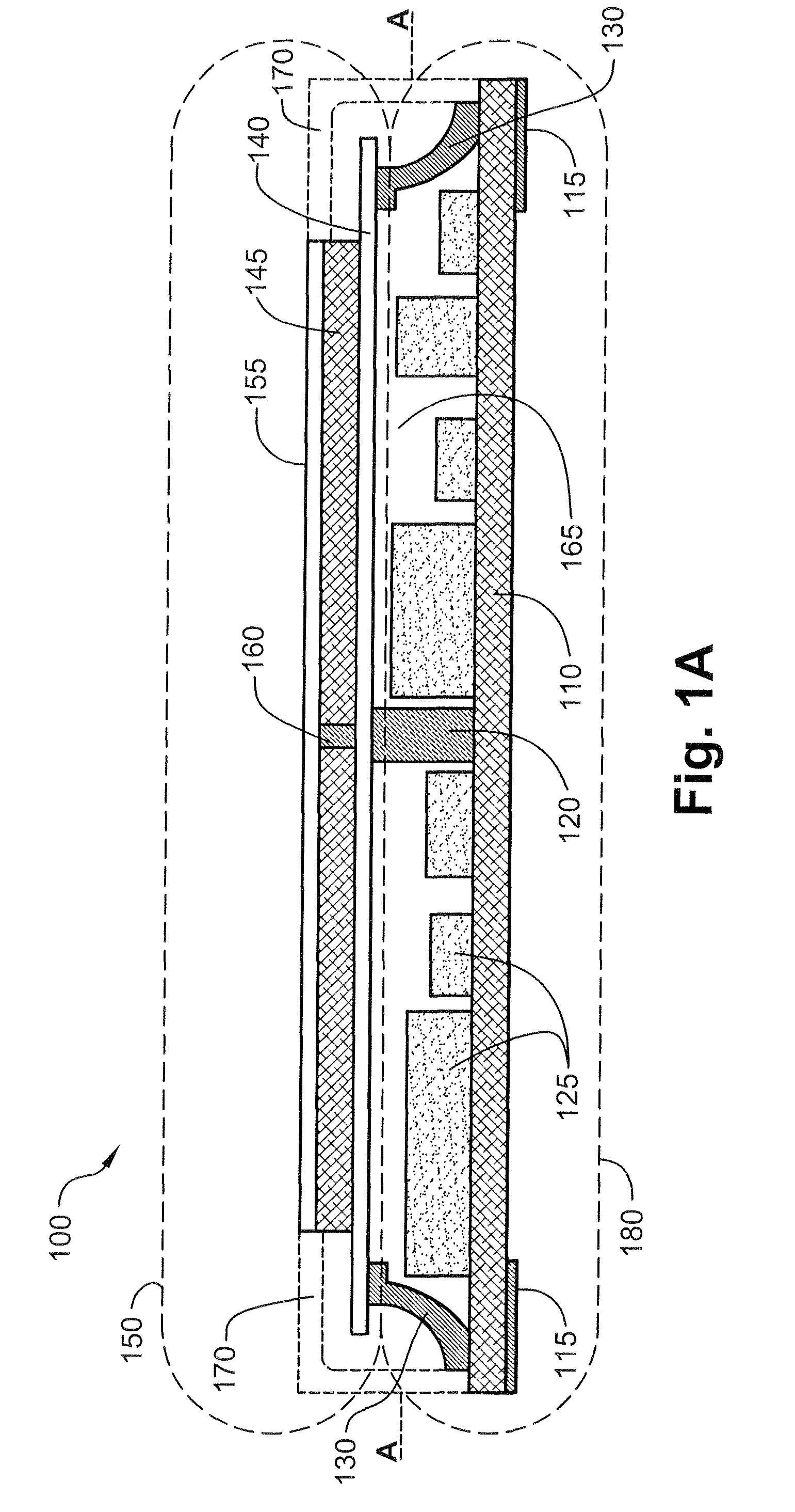
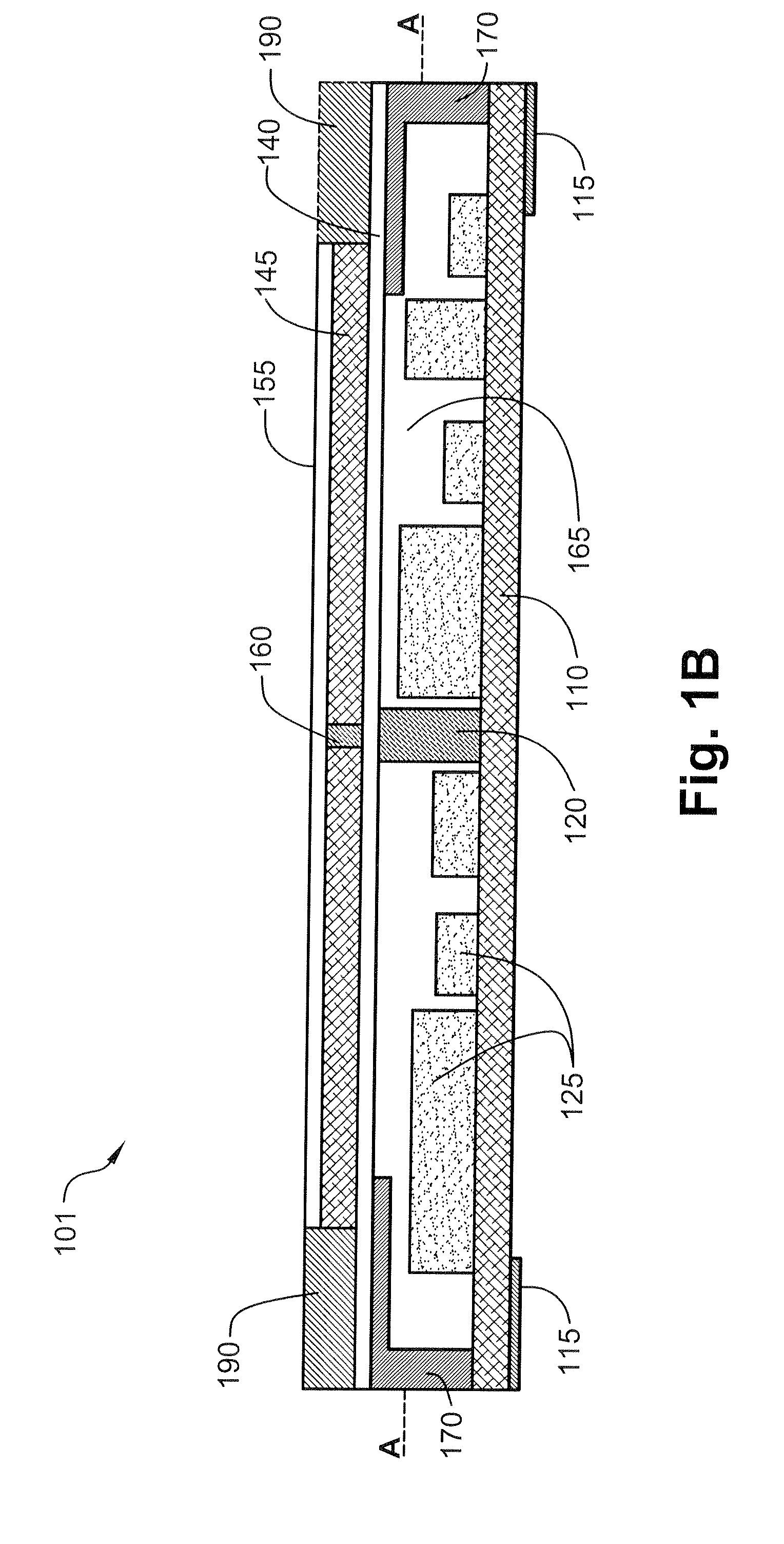
[0020]FIG. 1A is a cross sectional schematic illustration (AA) of a hybrid circuit 100 with an electronic circuit 180 and an integral planar patch antenna 150, according to an exemplary embodiment of the invention. In an exemplary embodiment of the invention, a substrate 110 (e.g. a PCB—printed circuit board) is used as a base for preparing circuit 100. Alternatively, other materials or constructions can be used to serve as the base for circuit 100. In an exemplary embodiment of the invention, various types of circuit elements 125 are used to construct circuit 100, for example circuit elements 125 may include:

[0021]1. Passive devices (e.g. resistors, capacitors);

[0022]2. Active devices, which require a power source for them to operate (e.g. integrated circuits, transistors), or

[0023]3. Other elements, for example discrete elements (e.g. diodes).

[0024]Optionally, some elements are embedded in substrate 110, some elements are surface mounted on substrate 110 and some are fitted into h...


PUM


Abstract

A circuit with an integral antenna, including a hybrid circuit on a substrate, a patch antenna that is adapted to be positioned at a pre-selected distance above the hybrid circuit and coupled to the hybrid circuit to form a single physical unit, a feeder that electronically connects between the hybrid circuit and the patch antenna.

Description

RELATED APPLICATIONS[0001]This application claims priority from Israeli application No. 173941 filed on Feb. 26, 2006, the disclosure of which is incorporated herein by reference.FIELD OF THE INVENTION[0002]The present invention relates generally to a hybrid circuit with an integral antenna.BACKGROUND OF THE INVENTION[0003]Nowadays people make use of many electronic devices on a daily basis, for example mobile telephones, GPS navigation systems, radios, MP3 players, PDAs, laptop computers, digital cameras and many other devices. It is a common interest for manufacturers to reduce the size of the circuits controlling the devices since the users are interested in small lightweight devices, which can easily be carried around. Additionally, there is an interest in combining devices together so that a single device can replace multiple devices. Thus a person can carry a single lightweight device, which performs the functions of a plurality of devices that they previously carried around.[...

Claims


Application Information

Patent Timeline
Patent Type & Authority Patents(United States)
IPC IPC(8): H01Q1/38H10N10/00
CPCH01L25/165H01Q9/0407H01Q23/00H01L2223/6677H01L2924/09701H01L2924/0002H01L2924/00H01L2924/19105H01L2924/3025
Inventor GOLDBERGER, HAIM
Owner ORIGIN GPS LTD
Learn More