Portable collapsible boat

a collapsible, boat technology, applied in the field of portable collapsible boats, can solve the problems of occupying a large space, severely restricting the shape, and both types of proposals have significant disadvantages, so as to reduce the overall weight of the new, the effect of less effort and less weight per foo

Inactive Publication Date: 2011-06-21
QUIGLEY WILLIAM J
View PDF5 Cites 26 Cited by
  • Summary
  • Abstract
  • Description
  • Claims
  • Application Information

AI Technical Summary

Benefits of technology

[0014]The invention relates to a boat that combines the best features of rigid hull boats with the best features of flexible hull boats without suffering from the drawbacks of rigid boats or folding boats. The present invention is easy to assemble and transport, lightweight, durable and rigid. Furthermore, the boat in accordance with the present invention easily adapts from paddling to sailing use and easily adapts from a single to a multiple passenger configuration.
[0016]The boat of the present invention comprises one or more rigid cockpit sections that may be fastened together by conventional mechanical means such as bolts or draw latches. In the preferred embodiment, the cockpit sections are detachably fastened together to provide versatility in the configuration of the rigid cockpit section. The cockpit sections are comprised of a rigid hull and rigid bulkheads, constructed of materials such as fiberglass, carbon fiber, plastic or wood. The bulkheads at the end of the cockpit sections form separate compartments with respect to the other sections of the boat and prevent water from entering the bow or stem sections in the event of a capsize, making the boat more seaworthy. The bulkheads also obviate the need for a watertight connection between sections.
[0017]In the present invention, the bow and stem sections are operatively connected to the rigid cockpit section. The connection of the bow and stem sections to the rigid cockpit section may be fixed or detachable. In the preferred embodiment, the bow and stem sections are detachably connected to the rigid cockpit section so that storage and transport are improved.
[0019]The result is that the portable collapsible boat of the present invention may be constructed using significantly lighter materials for the stringers of the bow and stern, and still be stiffer, which means that less effort is required to propel the boat through the water or carry the boat to and from the water. In addition, the weight per foot of conventional folding boats is higher than the weight per foot of rigid boats, which implies that the rigid cockpit decreases the overall weight of the new portable collapsible boat. Lastly, manufacture of the new portable collapsible boat is simpler than that of conventional folding boats because it has fewer parts and less dependence on precision stitching of the skin, because the skins cover a much smaller volume than in a conventional folding boat.

Problems solved by technology

Both types of proposals have significant disadvantages.
Collapsible boats having rigid hulls are durable, lightweight and stiff, but they either take up a significant amount of space when disassembled if the parts do not “nest” within each other, or they are severely constrained in their shape if the parts do nest within each other.
While portable collapsible boats having flexible hulls require little storage space and are easily transportable when collapsed, they suffer from several disadvantages.
The skin-on-frame construction of flexible hull boats is disadvantageous because:significant time and effort is required for assembly,structure lacks rigidity, resulting in poor performance,skin is fragile, particularly in the area where the operator's weight is concentrated,internal parts such as foot braces, seats, and padding are difficult to affix to the inside of the boat's flexible hull,extra equipment is required to convert the boat to sail, rather than paddle use,design lacks flexibility to accommodate both a single operator configuration and a multiple operator configuration,the overall weight is greater than that of rigid boats of the same type and size.

Method used


Image

  • Portable collapsible boat
  • Portable collapsible boat
  • Portable collapsible boat

Examples


Embodiment Construction

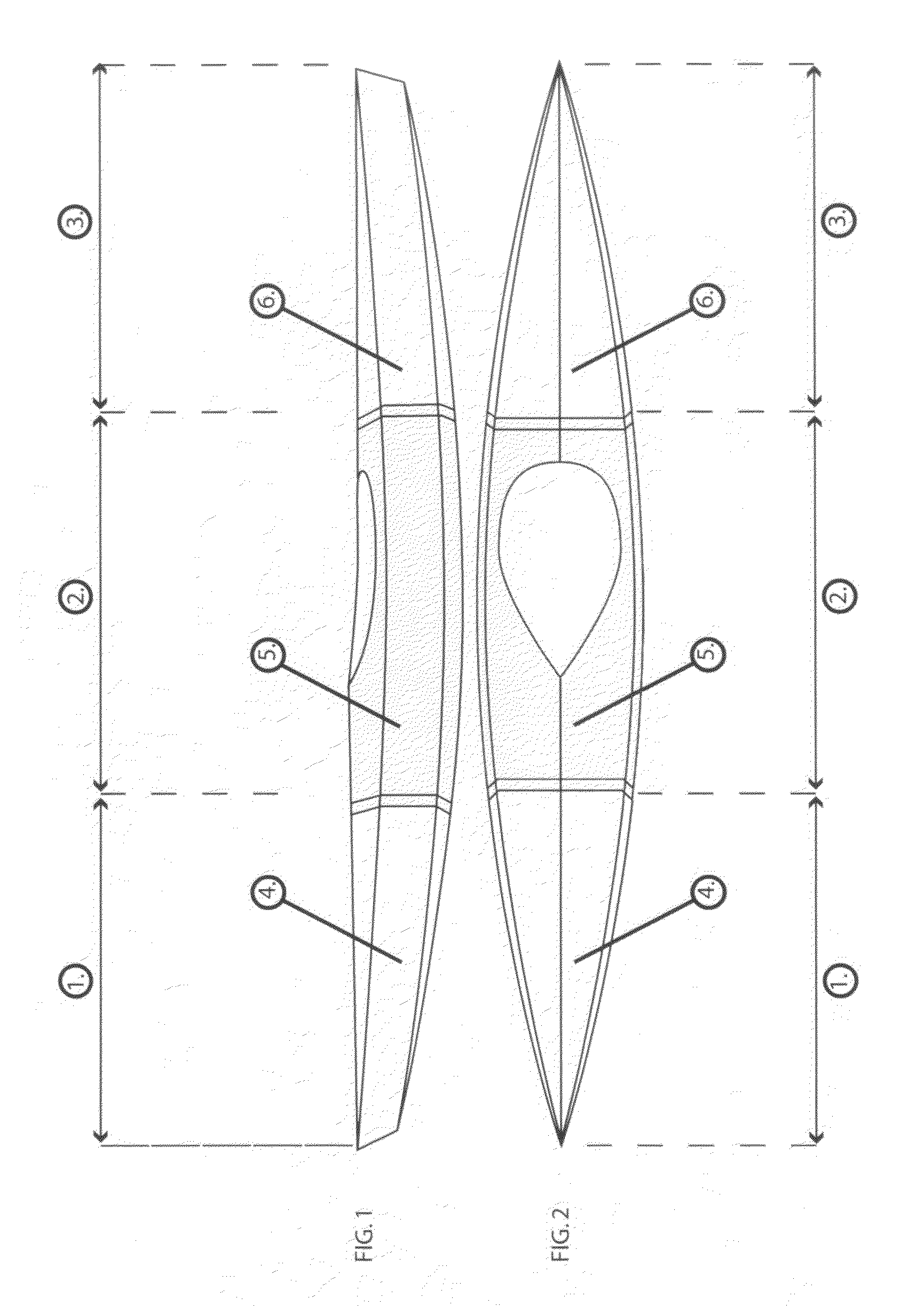
[0030]Referring now to FIGS. 1 and 2: (1) is the bow section, (2) is the rigid cockpit section, (3) is the stem section, (4) and (6) are the flexible skins of the bow and stem sections, and (5) is the rigid hull of the cockpit section of the boat of the present invention.

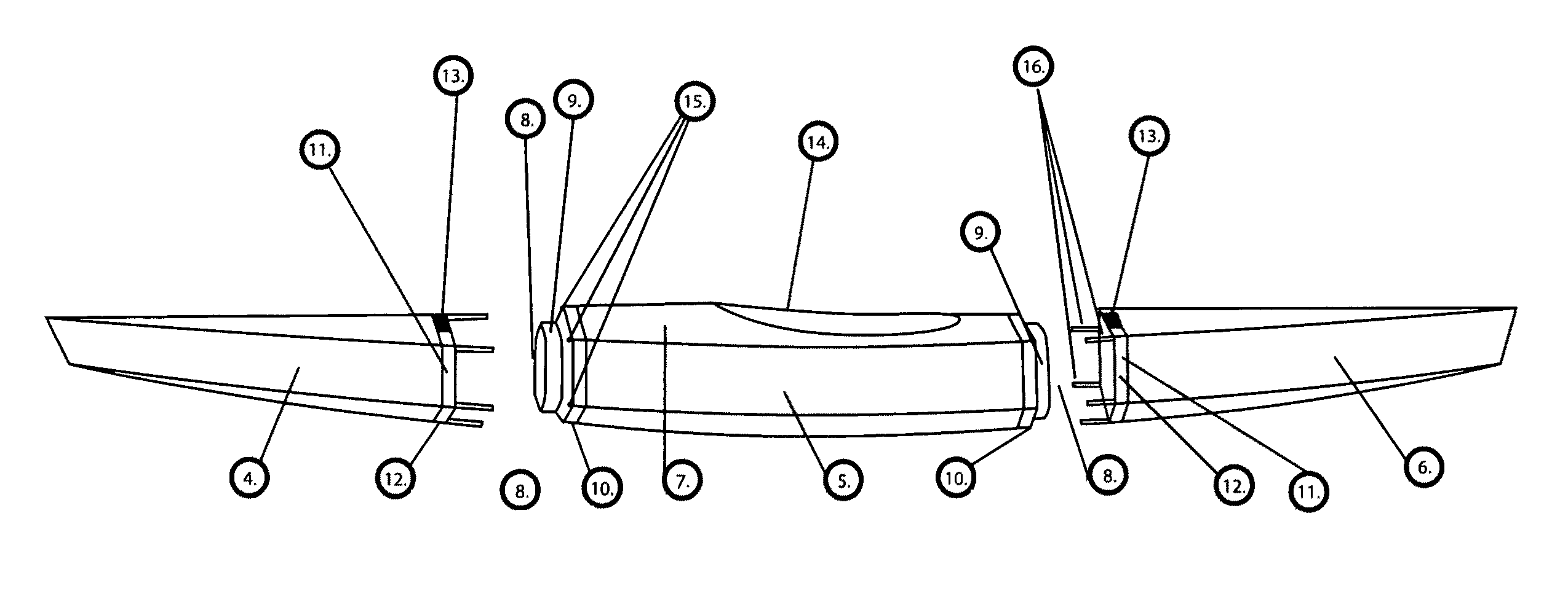
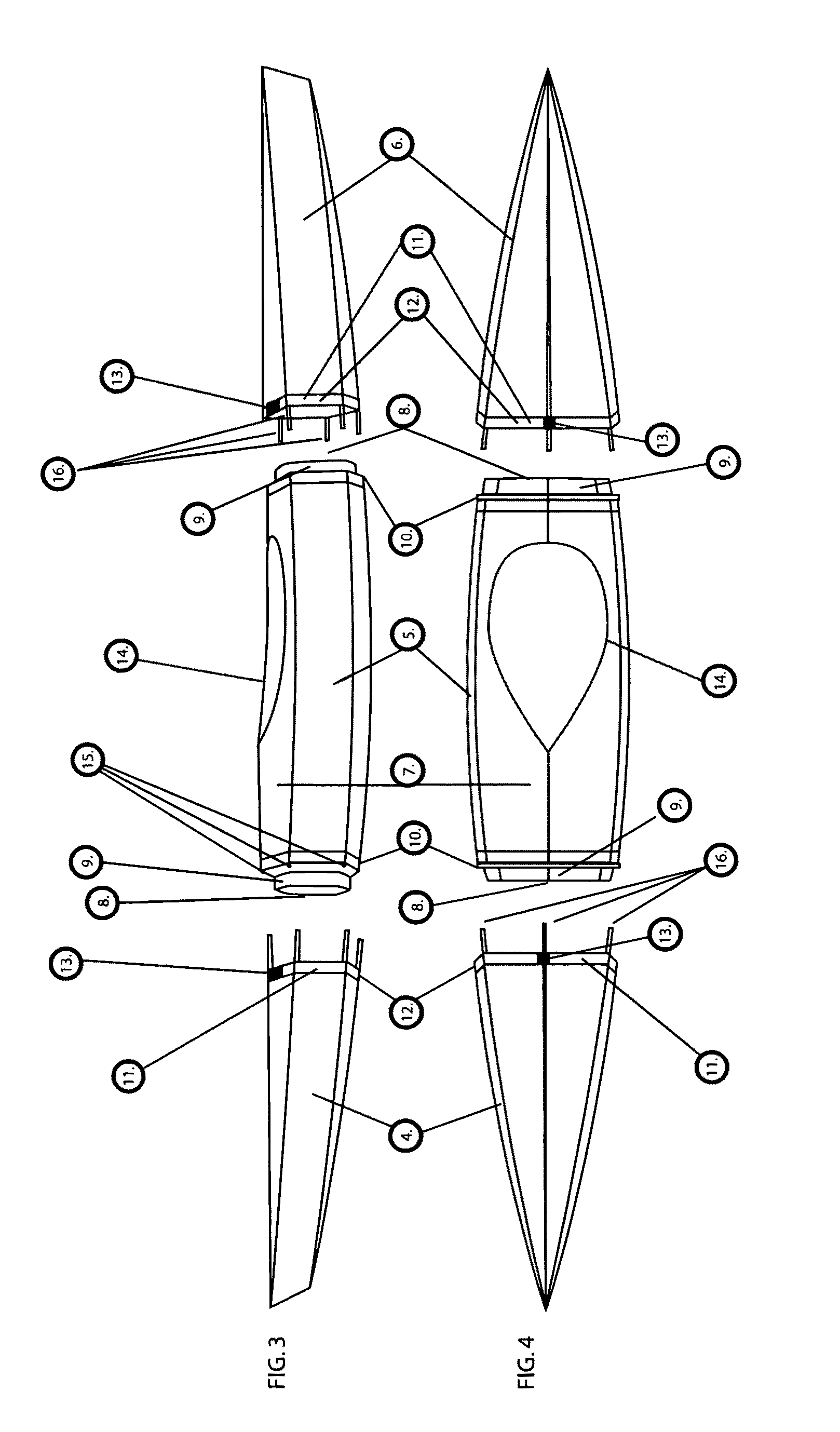
[0031]As shown in FIGS. 3 and 4, (7) is the rigid partial deck of the rigid cockpit section (2), (8) are the rigid bulkheads at the ends of the rigid cockpit section (2), (9) are the flanges, having the same cross sectional shape as the rigid cockpit section (2) but slightly smaller, (10) are the lips protruding from the circumferential surfaces of the bow and stem ends of the rigid cockpit section (2), (11) are the rigid battens encased within the skin of the bow (1) and stem (3) sections, (12) are the tensioning belts encased within the skin of the bow (1) and stem (3) sections, (13) are the buckles used to fasten the tensioning belts (12), (14) is the spray skirt flange, and (15) are the recesses in the rigid coc...


PUM


Abstract

The invention is a portable collapsible boat comprising one or more rigid cockpit sections, constructed of a material such as fiberglass, attached to a bow section and a stem section, which are constructed of fabric material covering a skeleton of longitudinal stringers and ring frames, and are attached to the rigid cockpit section(s) by means of a belt, buckles, and / or flanges. The hybrid folding boat combines the best features of rigid boats, such as performance and durability, with the best features of existing folding boats, such as transportability, without suffering from the drawbacks of rigid boats (mainly the extensive storage space required) or folding boats (mainly weight). The hybrid folding boat is lighter, easier to transport, more rugged, safer, easier to assemble, and stiffer than previous folding boats, adapts easily to a sailing rig, and facilitates one or more passengers. Manufacture of the boat is simpler than that of conventional folding kayaks because it has fewer parts and less dependence on precision stitching of the fabric covering.

Description

FIELD OF THE INVENTION[0001]This invention relates to a portable collapsible boat having a rigid cockpit section and skin-on-frame bow and stem sections. More particularly, the invention relates to a portable collapsible boat having particular utility as a kayak configurable for one or more than one paddler.BACKGROUND OF THE INVENTION[0002]Various proposals have been made to provide portable collapsible boats, ranging from rigid hull boats having detachable hull sections to flexible hull boats having a complete take-apart skeleton frame with removable skin. Both types of proposals have significant disadvantages.[0003]Conventional collapsible boats having rigid hulls rely on two or more rigid hull sections that couple or connect to form a boat. Collapsible boats having rigid hulls are durable, lightweight and stiff, but they either take up a significant amount of space when disassembled if the parts do not “nest” within each other, or they are severely constrained in their shape if t...

Claims


Application Information

Patent Timeline
Patent Type & Authority Patents(United States)
IPC IPC(8): B63B35/00
CPCB63B7/04B63B34/23
Inventor QUIGLEY, WILLIAM JOSEPH
Owner QUIGLEY WILLIAM J
Why Eureka
Try Eureka