Resonator assembly

a resonator and assembly technology, applied in the direction of combustion engines, engine components, electrical apparatus, etc., can solve the problems of not knowing the electrical parameters and neglecting the protection against high voltage, and achieve the effect of facilitating the mechanical construction reducing the cost of production, and ensuring the safety of the resonator assembly

Inactive Publication Date: 2011-06-21
DELPHI TECH INC
View PDF8 Cites 21 Cited by
  • Summary
  • Abstract
  • Description
  • Claims
  • Application Information

AI Technical Summary

Benefits of technology

[0008]An advantage of the invention lies firstly in the shape that can be achieved by the section-like sequence of generator section, inductance section, capacitance section and ignition section, namely a substantially elongate, cylindrical shape which allows easy introduction into the engine block of an internal combustion engine, the resulting total length of the resonator assembly also being useful so that the opening in the region of the ignition section is located in a section of the combustion chamber of the engine provided for this purpose when the resonator assembly is in the assembled state. The fact that all the above-mentioned sections are arranged in a common housing results in a shield for the electromagnetic fields that arise during operation, preventing surrounding functional units and assemblies from being influenced. But furthermore the functional units of the resonator assembly are themselves protected against any influences from the outside. For this purpose the housing is made of a conductive material or has at least one conductive surface. The need for a separate return conductor is eliminated, as the housing functions as a return conductor to the oscillatable dipole, which is formed by the electrical series circuit comprising inductance and capacitance sections.
[0009]Advantageous embodiments of the invention are the subject of the subsidiary claims. Back-references used here indicate further development of the subject of the main claim by the characteristics of the respective subsidiary claim; they are not meant as dispensation with obtaining independent objective protection for the combinations of characteristics of the subsidiary claims to which back-reference is made.
[0010]Furthermore, with respect to interpretation of the claims with a more detailed specification of a characteristic in a subsequent claim, it must be assumed that no such restriction exists in the preceding claims.
[0011]A mutual influence between the electrically operating components of generator section, inductance section and capacitance section can be avoided or at least reduced if these regions are arranged successively without overlap along the longitudinal axis. This facilitates firstly the mechanical construction of the resonator assembly, e.g. such that each section can be combined in segments with the or each adjacent section, e.g. by bolting, latching or the like, to form the resonator assembly. Secondly, undesirable mutual influences e.g. due to interactions between the resulting electromagnetic fields are reduced, so that the behaviour of the resonator assembly approaches an ideal resonator assembly with corresponding electrical components, and this can be understood with sufficient accuracy by mathematical modelling, which allows optimum control thereof for achieving on the one hand the voltage increase in the generator and on the other hand the voltage superelevation in the resonator.
[0012]The capacitance section is preferably designed as a metal cylinder which forms a section of the housing and of which the inner surface acts as an electrode and the outer surface acts as part of the return conductor, so that this section of the housing performs both the mechanical and electromagnetic protective function, the function as capacitance of the oscillating circuit of the resonator and lastly also the function as return conductor for the resonator assembly as a whole. A free end of such a metal cylinder then functions as an ignition section so that, in case of resonance, plasma forms within this free end, in particular directly in the edge region of the free end.
[0013]Preferably an inductance encompassed by the inductance section with a plurality of coil turns is oriented in such a way that a magnetic field which forms within the inductance during operation of the resonator assembly is coaxial with the longitudinal axis of the resonator assembly. For this purpose the coil turns are arranged on an (imaginary) cylinder wall all in the same plane. With respect to the design of the resonator assembly, the inductance therefore contributes substantially to its length; a diameter, that is, a width, and a depth of a surrounding enveloping contour remains small compared with the total length, so that the resonator assembly as a whole assumes a tubular contour, which makes it easier to introduce it into the engine block, sections located within the engine block when assembled being protected by the latter in addition. The generator section includes an electronic system which operates to excite the inductance and capacitance sections, connections for their external supply being passed through the housing. The electronic system is also protected electromagnetically and mechanically by the housing, so that when the oscillating circuits encompassed by the resonator assembly are excited, the function of the electronic system is not affected by external magnetic fields which would otherwise have a disturbing influence on these circuits. If the connections for external supply to the electronic system are passed through the housing, an opening in the housing which is necessary for external supply to the electronic system is limited to a minimum.

Problems solved by technology

A drawback of the resonator assemblies known in the state of the art lies above all in that electromagnetic parameters are not known in a manner required for optimum generation of plasma in the region of the spark gap.
With the resonator assembly described in DE 10 2006 037 246, a disadvantage also lies in that, due to the connection of the generator, a point between the inductance and capacitance of the generator is kept at earth potential, so that in an unfavourable manner the desired resonant frequency is influenced by external magnetic materials because the magnetic field is not spatially limited.
Lastly, known solutions also seem to neglect protection against the high voltage arising, or it is attempted to achieve possible protection by external means, e.g. a cap, a sleeve or the like.

Method used


Image

  • Resonator assembly
  • Resonator assembly
  • Resonator assembly

Examples


Embodiment Construction

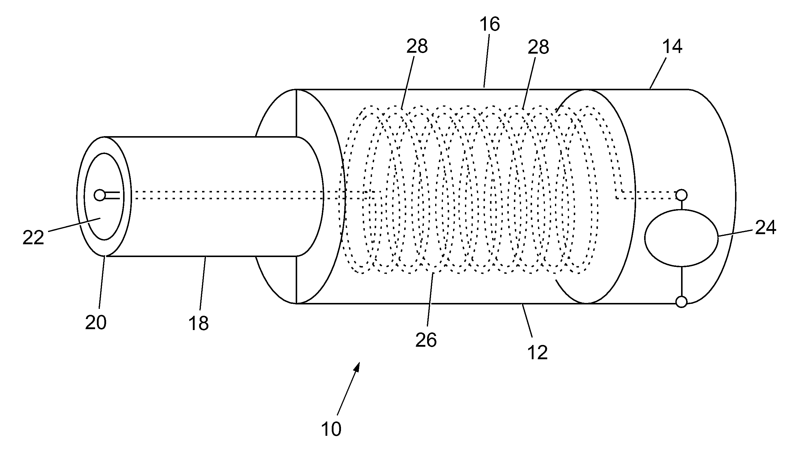
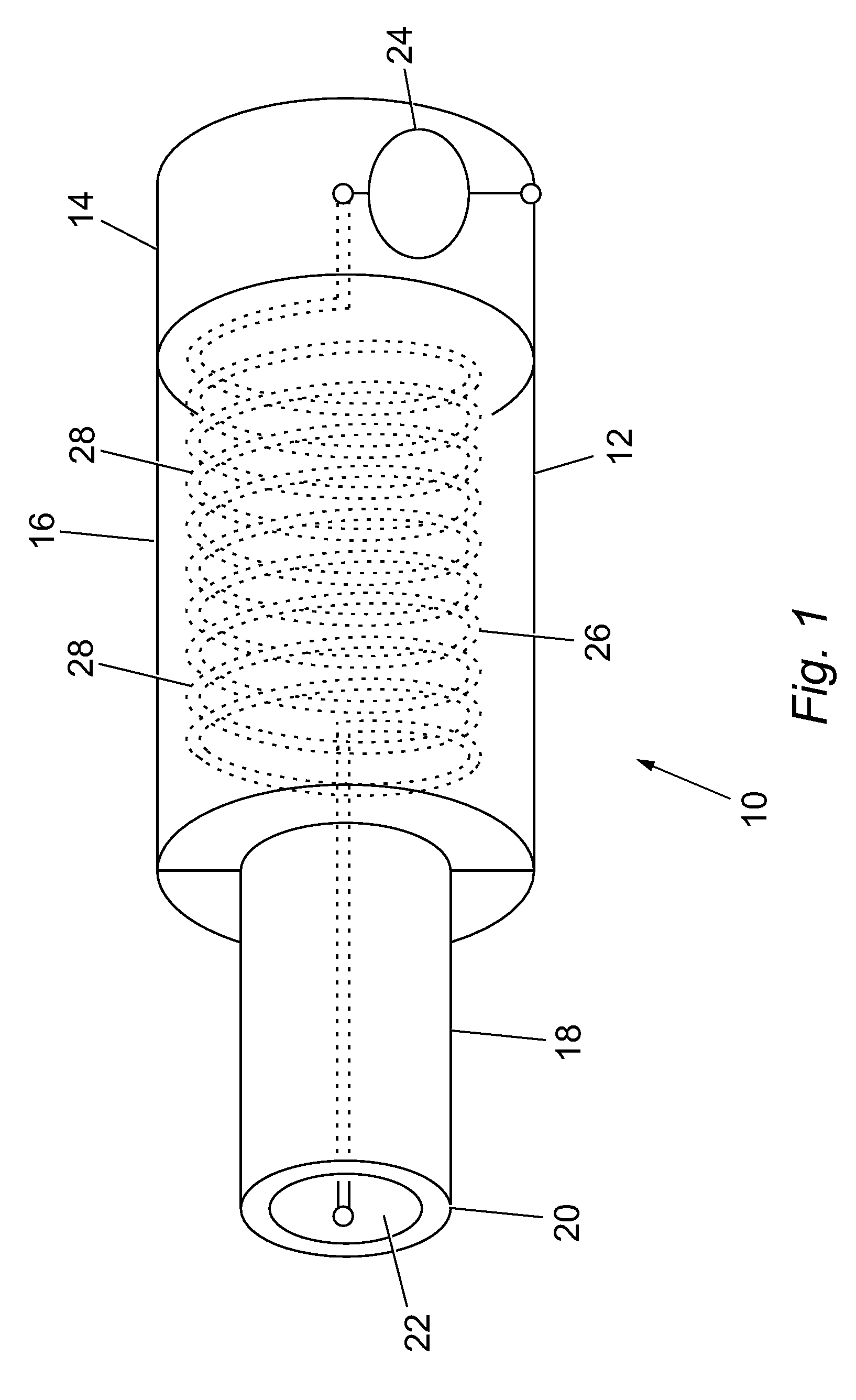
[0023]FIG. 1 shows a schematically simplified resonator assembly according to the invention, marked 10 as a whole. This includes, in a common housing 12, functional sections arranged in section-like fashion along a longitudinal axis, namely a generator section 14, an inductance section 16, a capacitance section 18 and an ignition section 20. The housing 12 surrounds all the above-mentioned functional sections and has an opening 22 in the region of the ignition section 20. The housing 12 is made of a conductive material or has at least one conductive surface.

[0024]The generator section 14 includes in a manner known in the art an electronic system 24, shown only schematically, which operates to excite the inductance section 16 and the capacitance section 18 and generates a voltage superelevation therein during operation. For this purpose the electronic system 24 includes its own oscillating circuit which is electromagnetically coupled to the inductance section 16, the oscillating circ...


PUM


Abstract

A resonator assembly is described having a longitudinal axis and generator section, an inductance section, a capacitance section, and an ignition section arranged in sections in a common housing along the longitudinal axis. The housing surrounds all the above-mentioned sections and has an opening in the region of the ignition section, and the housing is made of an electrically conductive material or has at least one conductive surface. An electrical series circuit comprising an inductance section and capacitance section constitutes electrically an oscillatable dipole to which the housing acts as a return conductor.

Description

TECHNICAL FIELD[0001]The invention concerns a resonator assembly for generating ignition energy for the combustion of gas mixtures.BACKGROUND OF THE INVENTION[0002]The invention concerns a resonator assembly for generating ignition energy for the combustion of gas mixtures, which in a manner known in the art as a functional element includes a generator in a generator section, a voltage increase being sought by suitable excitation in an oscillating circuit encompassed thereby, a resonator section mounted functionally behind the generator section and electromagnetically coupled thereto and having a further oscillating circuit which for this purpose includes at least one inductance, and an ignition section.[0003]In the resonator coupled to the generator, a voltage superelevation is to arise during operation, which with the continuous supply of energy from the generator can attain 100 to 200 times the voltage fed to the resonator from the generator, while in the section in front, that i...

Claims


Application Information

Patent Timeline
Patent Type & Authority Patents(United States)
IPC IPC(8): H01T13/42H01T13/44
CPCH01T13/44
Inventor HEISE, VOLKER
Owner DELPHI TECH INC
Why Eureka
Try Eureka