
Process and apparatus for release and recovery of methane from methane hydrates

a technology of methane hydrate and process, which is applied in the field of recovery methods and equipment or systems for methane from methane hydrate, can solve the problems of increasing the energy consumption of methane hydrate, reducing reducing the expenditure of energy. , to achieve the effect of increasing the net heating value of methane recovered, reducing the expenditure of energy required

Inactive Publication Date: 2011-06-21
GAS TECH INST
View PDF13 Cites 27 Cited by
  • Summary
  • Abstract
  • Description
  • Claims
  • Application Information

AI Technical Summary

Benefits of technology

This patent describes a process and system for releasing and recovering methane from underground methane hydrate deposits. The process involves heating the methane hydrate deposit with a combustion oxidant to create heated CO2, which is then introduced directly into the deposit to displace methane. The displaced methane is then either diverted back into the combustion process or recovered for use in other applications. This process reduces energy consumption and costs compared to conventional methods. The system includes a combustion oxidant conduit, a combustor, and a displaced methane conduit. The combustor can be either a catalytic or non-catalytic combustor.

Problems solved by technology

While global estimates vary considerably, the energy content of methane occurring in hydrate form is immense, possibly exceeding the combined energy content of all other known fossil fuels.
However, future production volumes are speculative because methane production from hydrate has not been documented beyond small-scale field experiments.
It has been found, however, that, because of heat losses incurred during transmission of the heated fluid to the methane hydrate deposit, the amount of energy required to supply the required heat into the methane hydrate deposit nearly equals the heating value of the released methane.
In-situ combustion could reduce such heat losses, but is said to be difficult to establish in a hydrate deposit and would result in undesirably high hydrate deposit temperatures.
To date, no such mining system has been demonstrated to be economically feasible.
However, at the temperatures of the methane hydrate deposit, the reaction is prohibitively slow.
Disadvantageously, all of the fluids, i.e. fuel, oxidizer, and CO2, required for implementation of this method are transported from sources above ground to the methane hydrate deposit, requiring substantial expenditures of energy and reducing the net heating value of the extracted methane.

Method used


Image

  • Process and apparatus for release and recovery of methane from methane hydrates
  • Process and apparatus for release and recovery of methane from methane hydrates
  • Process and apparatus for release and recovery of methane from methane hydrates

Examples


Embodiment Construction

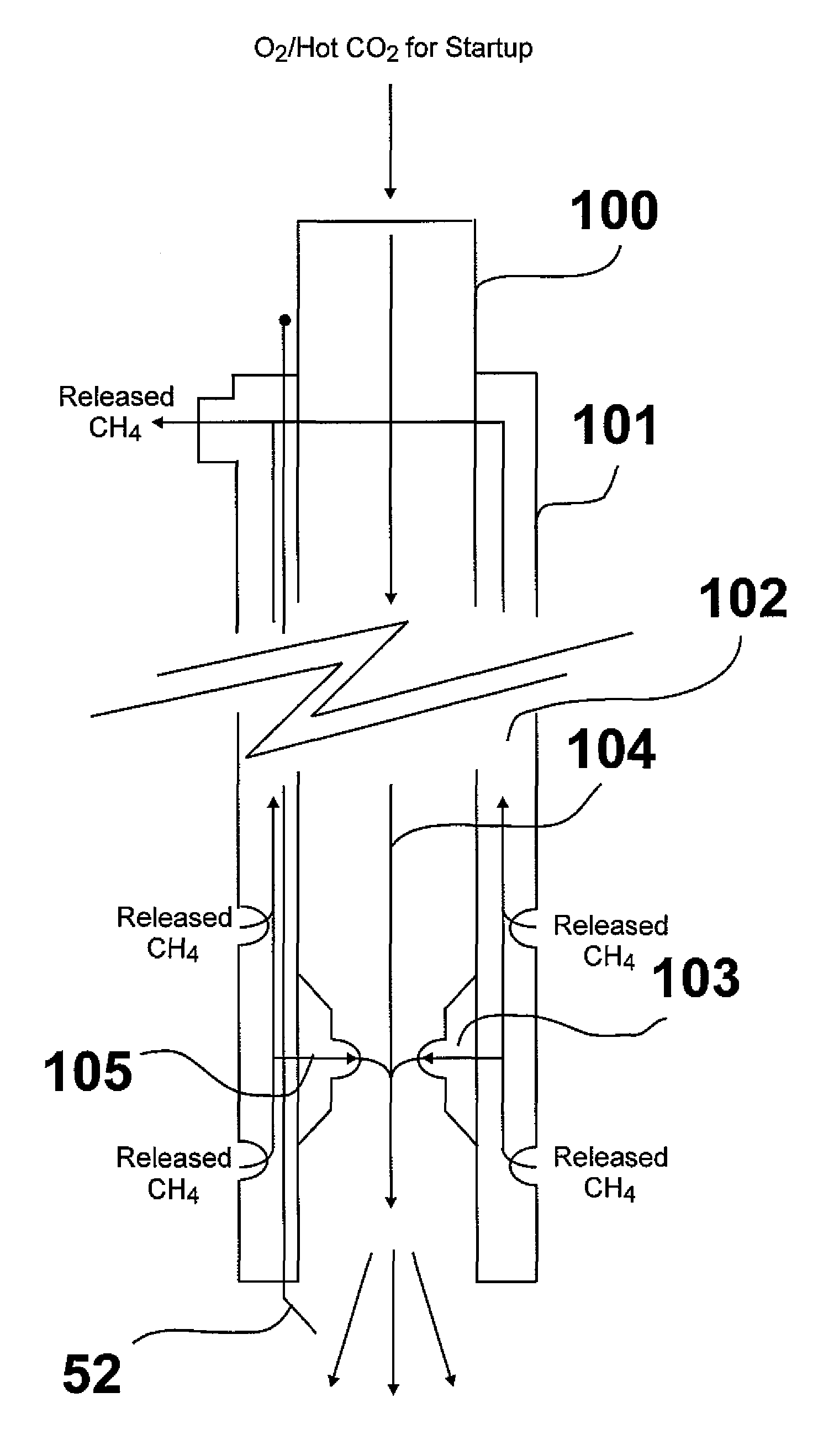
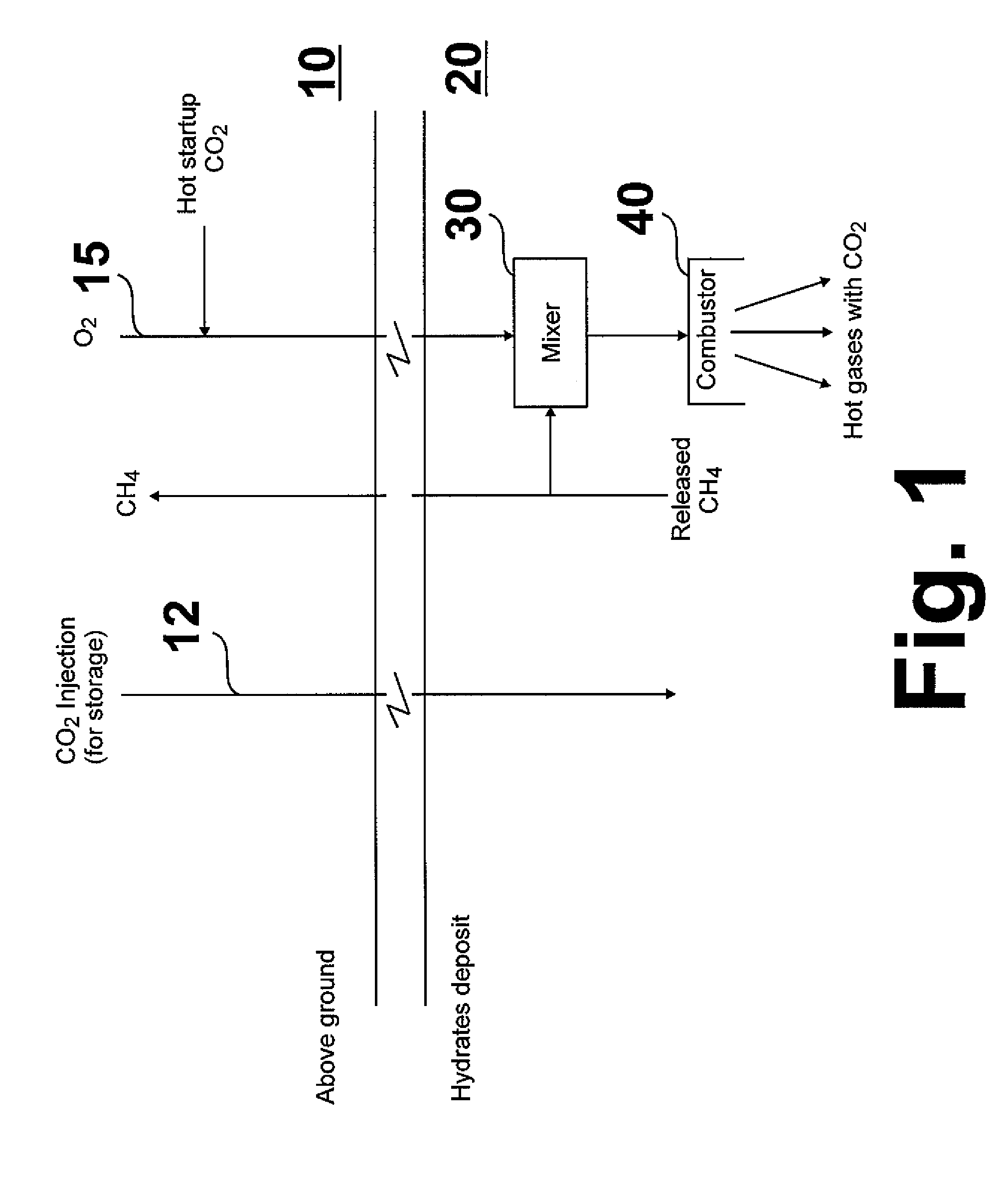
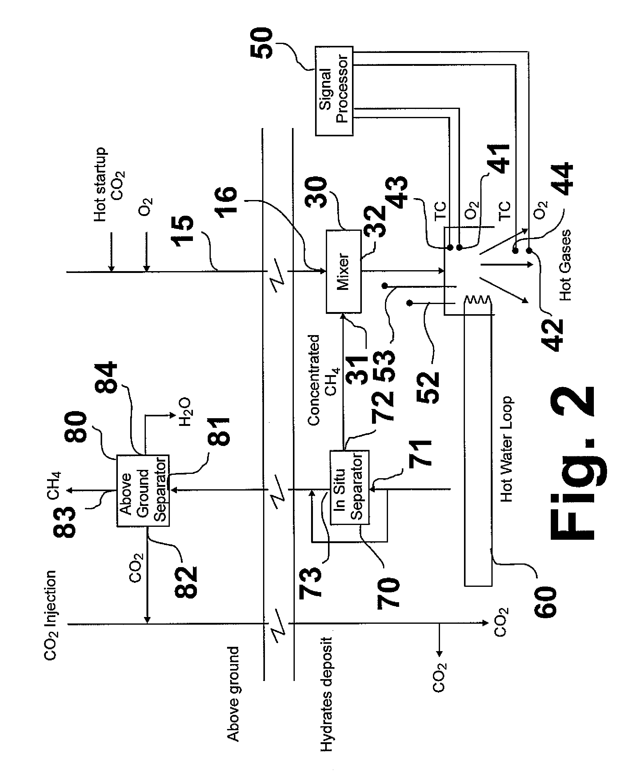
[0017]The basic principle of this invention, shown in FIG. 1, as compared with conventional methods and systems, is the direct utilization of methane released from a methane hydrate deposit as a source of heat and carbon dioxide for sustaining the release and recovery of methane process. As shown therein, a combustion oxidant, e.g. oxygen, is introduced from above ground, generally designated as 10, through a conduit 15 into a methane hydrate deposit, generally designated as 20. The combustion oxidant is introduced into a mixer 30 proximate the methane hydrate deposit in which it is mixed with a portion of combustion methane. The resulting mixture is then introduced into a combustor 40 in which the combustion methane and combustion oxidant react, forming heated combustion products, which includes heated carbon dioxide. The heated carbon dioxide contacts the methane hydrate deposit resulting in dissociation of the methane therein and formation of CO2 hydrate. A portion of the dissoci...


PUM


Abstract

A process and system for release and recovery of methane from subterranean methane hydrate deposits in which heated CO2 is used to displace methane from the methane hydrate deposits and a portion of the displaced methane is routed to a combustion device proximate the deposit for combustion in-situ, generating heated CO2 which is introduced into the deposit, displacing additional methane, a portion of which is routed to the combustion device, thereby providing a substantially self-sustaining process. Portions of the displace methane not routed to the combustion device are captured for use elsewhere.

Description

BACKGROUND OF THE INVENTION[0001]1. Field of the Invention[0002]This invention relates to a method and apparatus or system for recovering methane from methane hydrates. In one aspect, this invention relates to a method and apparatus for recovering methane from subterranean methane hydrate deposits. In another aspect, this invention relates to a method and apparatus for in situ recovery of methane from subterranean methane hydrate deposits.[0003]2. Description of Related Art[0004]Methane hydrate, also known as methane clathrate, is a cage-like lattice of ice inside which are trapped molecules of methane, the primary component of natural gas. If methane hydrate is either warmed or depressurized, it reverts back to methane and water. Methane hydrate fields or deposits generally occur under the Arctic permafrost or beneath the ocean floor. While global estimates vary considerably, the energy content of methane occurring in hydrate form is immense, possibly exceeding the combined energy ...

Claims


Application Information

Patent Timeline
Patent Type & Authority Patents(United States)
IPC IPC(8): E21B36/00E21B36/02E21B43/24E21B43/38E21B47/06
CPCE21B36/02E21B41/0064E21B43/243Y02C10/14E21B2043/0115E21B41/0099Y02C20/40
Inventor KHINKIS, MARK J.ABBASI, HAMID A.PERRY, KENT
Owner GAS TECH INST
Learn More