Surveying device and surveying system

a technology of surveying system and surveying device, which is applied in the direction of distance measurement, using reradiation, instruments, etc., can solve the problems of short measuring time of one measurement, reduced optical density reduced optical intensity of each distance measurement light, so as to achieve high accuracy and high accuracy. the effect of not decreasing the optical density

Active Publication Date: 2011-06-21
KK TOPCON
View PDF13 Cites 8 Cited by
  • Summary
  • Abstract
  • Description
  • Claims
  • Application Information

AI Technical Summary

Benefits of technology

[0011]It is an object of the present invention to provide a surveying device and a surveying system, by which it is possible to perform a multi-measurement on a multiple points at the same time, and also to perform the one-man operated measurement, and to accomplish the measurement with high accuracy.
[0016]The present invention provides a surveying device, comprising a light source for emitting a distance measuring light, an elevation rotary mirror for deflecting the distance measuring light in a direction toward an object to be measured, a high-speed deflection mirror for deflecting the distance measuring light at a speed higher than the elevation rotary mirror, a distance measuring light projecting unit for projecting the distance measuring light, and an arithmetic control unit for controlling driving of the high-speed deflection mirror and the elevation rotary mirror. As a result, in case where there are a plurality of objects to be measured in wide range, the measurement can be performed on a plurality of objects to be measured at the same time by projecting the fan-shaped beam in rotary irradiation. And in case where there is an object to be measured, the measurement can be performed with high accuracy by projecting the spot-type light. Accordingly, the measurement in wide range and the measurement with high accuracy can be performed on a plurality of objects to be measured by a single surveying device. Further, optical density is not decreased and the measurement can be performed for the long distance because the fan-shaped distance measuring light can be formed by amplifying spot-type lights.
[0017]Also, the present invention provides the surveying device as described above, further comprising a fan-shaped beam projecting unit for projecting two or more fan-shaped beams with at least one of the fan-shaped beams being tilted, a fan-shaped beam receiving unit for receiving the reflected fan-shaped beam reflected from the object to be measured, and a fan-shaped beam projecting direction detecting unit for detecting a fan-shaped beam projecting direction of the fan-shaped beam projecting unit, wherein the arithmetic control unit calculates a direction of the object to be measured based on signal from the fan-shaped beam receiving unit and from the fan-shaped beam projecting direction detecting unit. As a result, it is possible to obtain the reflection light from the object to be measured quickly and accurately, an efficiency of the surveying operation is improved.
[0018]Further, the present invention provides a surveying system, which comprises a surveying device and an object to be measured, wherein the surveying device comprises a distance measuring light projecting unit, which has a light source for emitting a distance measuring light, an elevation rotary mirror for deflecting the distance measuring light in a direction toward an object to be measured, and a high-speed deflection mirror for deflecting the distance measuring light at a speed higher than the elevation rotary mirror, for projecting the distance measuring light, a projecting direction detecting unit for detecting a projecting direction of the distance measuring light from the distance measuring light projecting unit, a distance measuring unit for measuring a distance based on a reflection light from the object to be measured, a fan-shaped beam projecting unit for projecting two or more fan-shaped beams, with at least of one of the fan-shaped beams being tilted, in rotary irradiation, a first communication unit, and an arithmetic control unit for controlling a driving of the elevation rotary mirror and the high speed deflecting mirror, and wherein the object to be measured has a reflector for reflecting the distance measuring light, a fan-shaped beam receiving unit for receiving the fan-shaped beams, and a second communication unit for transmitting a signal from the fan-shaped beam receiving unit to the first communication unit. As a result, data and an information of measurement can be given and taken between the surveying device and the object to be measured, and it is possible to perform the measurement in wide range with high working efficiency.

Problems solved by technology

As a result, an optical intensity of each of the distance measuring light is decreased, and influence of noise light becomes stronger, and this leads to lower measurement accuracy.
Further, because the distance measuring light is rotated at high velocity, a measuring time of one measurement is short.
Also, there are not many distance measurement data to be averaged, and it is not possible to improve the measurement accuracy.
Thus, these are a problem that the distance which can be measured is lengthen, and other problems.
The measurement can be made with high accuracy and a working efficiency of the measurement is also high, but it is not possible to perform measurements at a multiple points at the same time.
As a result, in case it is necessary to perform measurements on a multiple points at the same time, the working efficiency is extremely decreased.

Method used


Image

  • Surveying device and surveying system
  • Surveying device and surveying system
  • Surveying device and surveying system

Examples


first embodiment

[0048]Now, referring to FIG. 3 to FIG. 7, a description will be given below on the present invention.

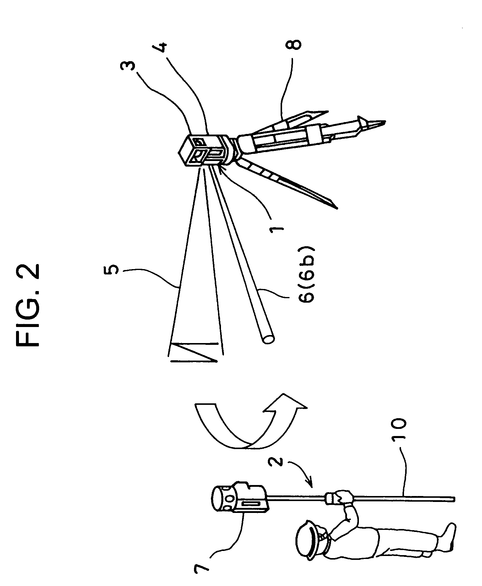
[0049]The surveying device 1 primarily comprises a leveling unit 11, a main unit 12 mounted on a tripod 8 (see FIG. 2) via the leveling unit 11, and a rotator 13, which is rotatably mounted on the main unit 12.

[0050]The leveling unit 11 is used to perform the leveling of the surveying device 1 and the leveling unit 11 has a point laser beam projecting unit 14, which projects laser beams downward in vertical direction. The position where the surveying device 1 is installed can be determined by a point on a ground surface where the point laser beam is projected.

[0051]A distance measuring unit 15, a distance measuring optical unit 16, an elevation rotation axis tilt detecting unit 17, a tilt sensor 10, a main unit controller 19, a communication unit 21, a power source 22, etc. are accommodated in the main unit 12.

[0052]The distance measuring unit 15 has a distance measuring light source...

second embodiment

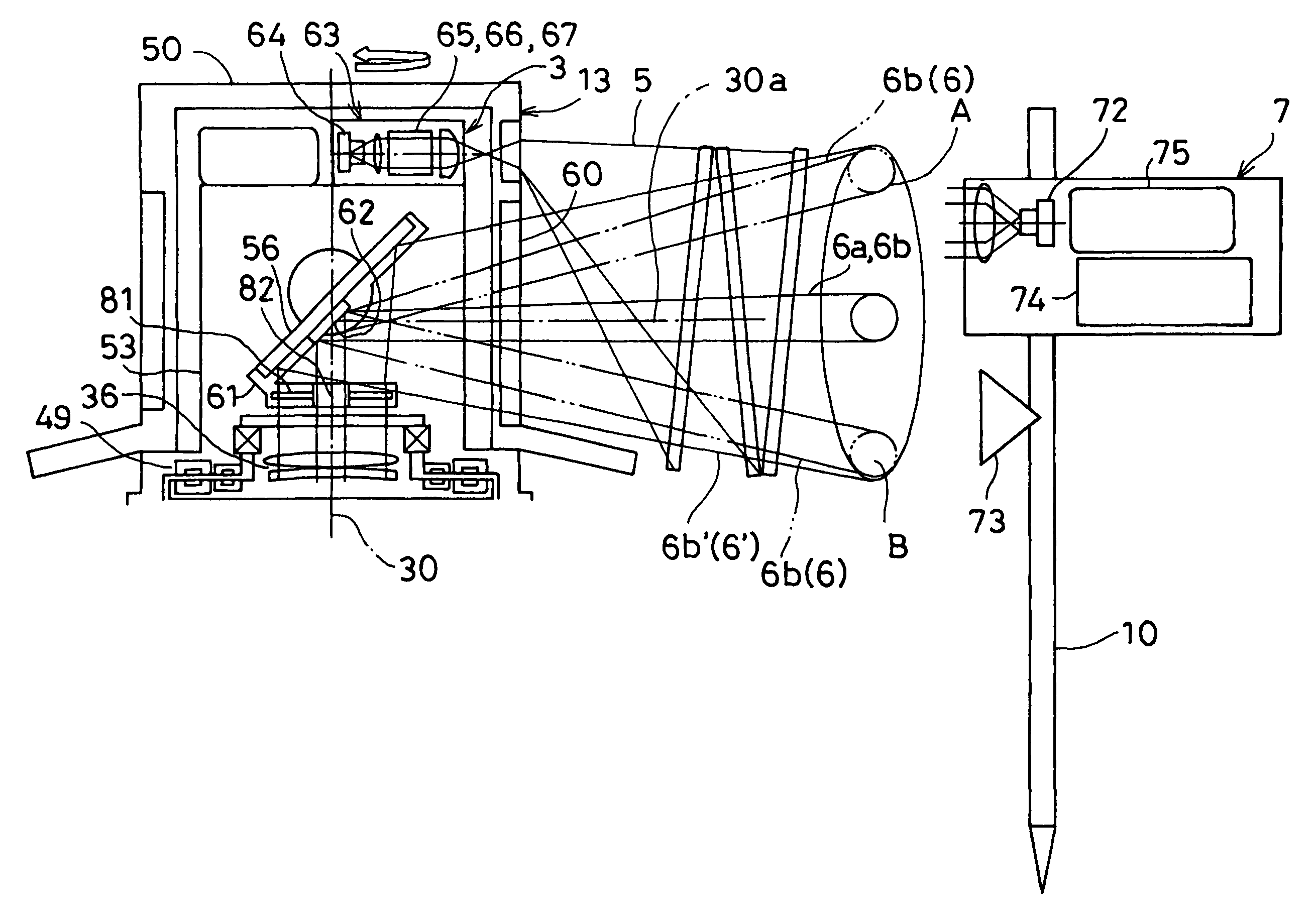
[0110]FIG. 9 is a diagram to explain a locus of the distance measuring light 6, which is projected in the In FIG. 9, a symbol C denotes a locus of a horizontal distance measuring optical axis 30a, i.e. a locus of the distance measuring light 6 in case where the distance measuring light is reflected only by tilting of the high-speed deflection mirror 62 when the high-speed deflection mirror 62 is not vibrated. A symbol D represents an actual locus of the distance measuring light 6 in case where the high-speed deflection mirror 62 is vibrated, and further, the elevation angle of the high-speed deflection mirror 62 is changed. In FIG. 9, reference numeral 73 denotes a prism of the object 2 to be measured. When the locus D passes through the prism 73, the reflected distance measuring light 6′ is obtained.

[0111]In the second embodiment, the elevation angle of the high-speed deflection mirror 62 is controlled based on the horizontal angle and the elevation angle of the object 2 to be mea...

third embodiment

[0115]Now, referring to FIG. 10 and FIG. 11, a description will be given on the invention.

[0116]In the third embodiment, it is so designed that the distance measuring light 6 entering the distance measuring optical unit 16 are vibrated by the high-speed deflection mirror 62.

[0117]In FIG. 10 and FIG. 11, the equivalent components as shown in FIG. 3 and FIG. 4 are represented by the same symbols, and a detailed description is not given here.

[0118]In the third embodiment, the high-speed deflection mirror 62 is applied as a mirror 33a (see FIG. 5) used in the first embodiment.

[0119]First, a description will be given on a general feature of the optical system of the distance measuring unit 15.

[0120]A laser diode 85 is a light emitting source to emit the distance measuring light 6. A half-mirror 86 is disposed on an optical axis of the laser diode 85. By the half-mirror 86, a part of the distance measuring lights 6 is reflected as an internal reference light 87. Then, the part of the dist...


PUM


Abstract

The present invention provides a surveying device, which comprises a light source for emitting a distance measuring light 6, an elevation rotary mirror 56 for deflecting said distance measuring light in a direction toward an object to be measured, a high-speed deflection mirror 62 for deflecting said distance measuring light at a speed higher than said elevation rotary mirror, a distance measuring light projecting unit for projecting said distance measuring light, and an arithmetic control unit for controlling driving of said high-speed deflection mirror and said elevation rotary mirror.

Description

BACKGROUND OF THE INVENTION[0001]The present invention relates to a surveying device and a surveying system when a surveying operation is performed by a single surveying operator or by cooperation of two or more surveying operators.[0002]In a surveying operation performed in a civil engineering work, e.g. a surveying operation in a road construction, a measurement is performed on positions on both sides of the road, on a difference in elevation, on a width of the road, etc., and a plurality of measuring points are measured at the same time. As a result, the surveying operation is a cooperative operation to be performed by two or more surveying operators.[0003]A surveying device, by which measurement can be made on a plurality of measuring points at the same time, is disclosed in JP-A-2006-337302.[0004]In a surveying device according to JP-A-2006-337302, laser beams for forming reference plane including three or more fan-shaped laser beams, with at least one of the laser beams being ...

Claims


Application Information

Patent Timeline
Patent Type & Authority Patents(United States)
IPC IPC(8): G01C3/08
CPCG01C15/004G01S17/42G01S7/4817
Inventor HAYASHI, KUNIHIROOHTOMO, FUMIOKUMAGAI, KAORU
Owner KK TOPCON
Why Eureka
Try Eureka