Device for limiting field on which radiation is irradiated

a technology of radiation limiting and aperture leaf, which is applied in the direction of diaphragm/collimeter handling, nuclear engineering, therapy, etc., can solve the problems of reducing the position accuracy of the aperture leaf, difficult to accurately form the irradiation field, and difficult to form the aperture leaf with a reduced thickness, etc., to achieve the effect of accurately formed and sufficiently reduced thickness of the aperture lea

Inactive Publication Date: 2011-06-21
RIGHT MFG
View PDF18 Cites 29 Cited by
  • Summary
  • Abstract
  • Description
  • Claims
  • Application Information

AI Technical Summary

Benefits of technology

[0035](1) In the irradiation field limiting device according to the present invention, the flexible linear member is secured to the thick portion of each of the aperture leaves arranged in the thickness direction and which shield radiation from the radiation source, and the driver section drives the linear member a specific amount.
[0036]According to this irradiation field limiting device, since it suffices that the aperture leaf have such a thickness that the linear member can be secured to the aperture leaf, the thickness of the aperture leaf can be sufficiently reduced.
[0037](2) In the irradiation field limiting device according to the present invention, the driver section includes the slider which moves along the axial direction of the drive shaft accompanying rotation of the drive shaft inserted into the base, and the flexible linear member is connected with the slider.
[0038]According to this irradiation field limiting device, since the aperture leaf to which the linear member is secured can be driven due to the movement of the slider accompanying the rotation of the drive shaft, the irradiation field can be accurately formed.
[0039](3) In the irradiation field limiting device according to the present invention, the connection portion includes the torque limiter section (driving force limiting section) which limits transmission of torque (driving force) equal to or greater than a specific torque.

Problems solved by technology

The irradiation field limiting device disclosed in the patent document 1 has a problem in which the positional accuracy of the aperture leaf decreases due to wear of the rack and the pinion.
Therefore, it is difficult to accurately form the irradiation field.
This makes it difficult to form an aperture leaf with a reduced thickness.
As a result, a large number of aperture leaves cannot be disposed in a limited installation space.
Therefore, it is difficult to ensure stable operation over a long period of time since the ridges easily wear and exhibit poor lubricity.
The irradiation field limiting device disclosed in the patent document 2 has a problem in which it is difficult to form a thin aperture leaf because the groove is formed in the sliding surface of the aperture leaf.

Method used


Image

  • Device for limiting field on which radiation is irradiated
  • Device for limiting field on which radiation is irradiated
  • Device for limiting field on which radiation is irradiated

Examples


first embodiment

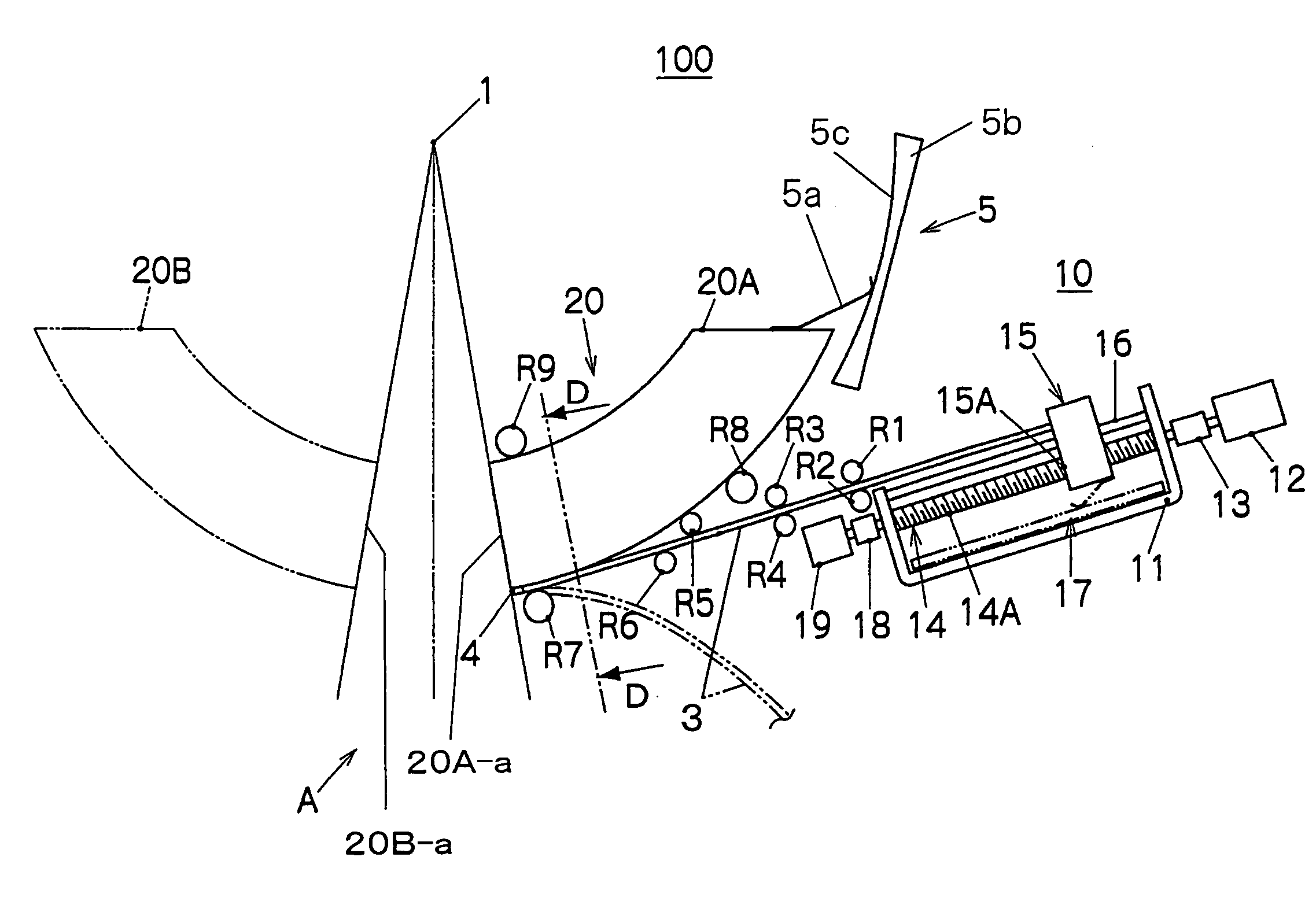
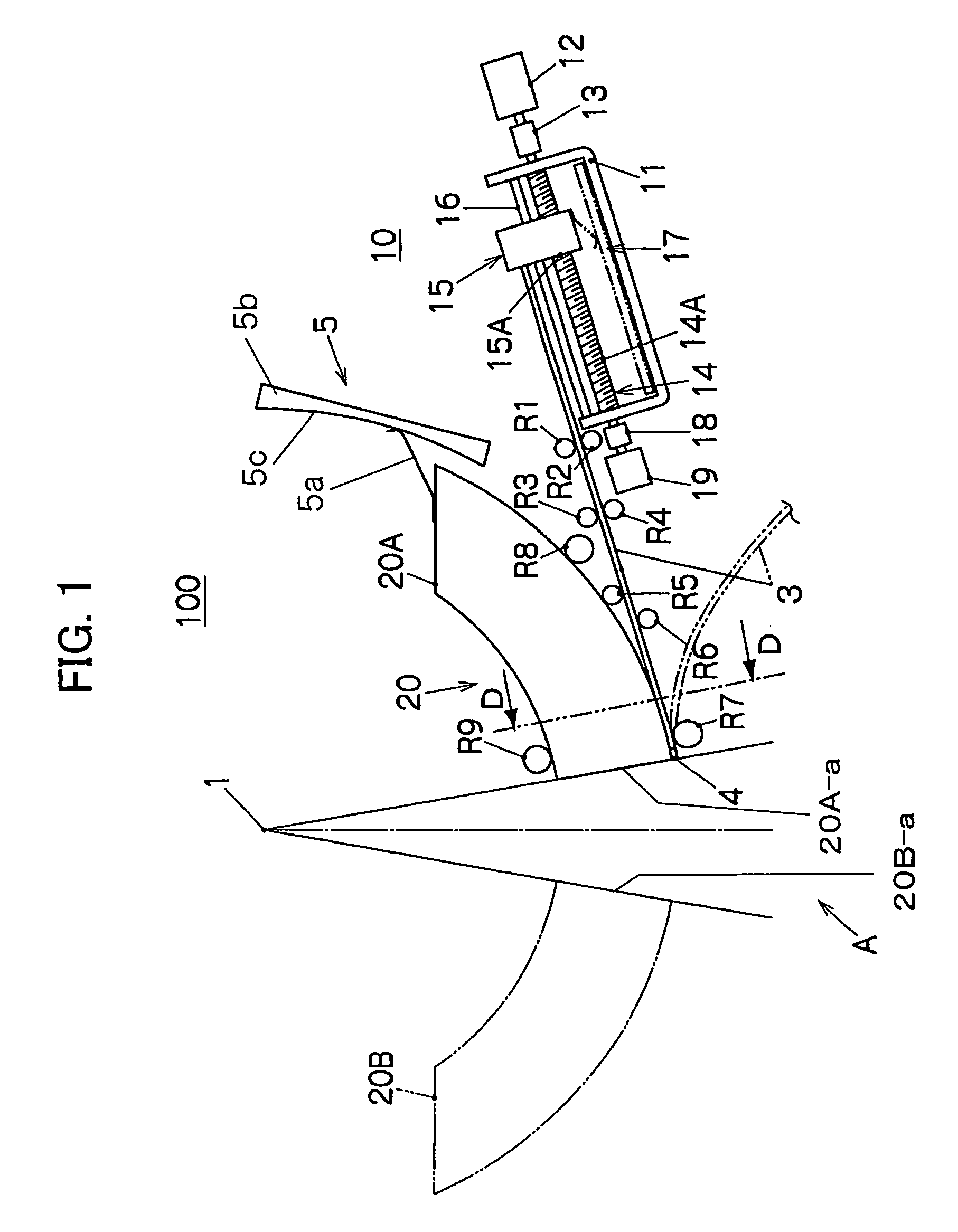
[0104]FIG. 1 is a view showing an irradiation field limiting device 100 according to a first embodiment of the present invention.

[0105]The irradiation field limiting device 100 is a device for shielding radiation from a radiation source 1 to limit an irradiation field A to a desired range, the device including an aperture leaf 20, a flexible linear member 3 secured to the thick portion of the aperture leaf 20, a driver section 10 which drives the linear member 3 a specific amount, and the like.

[0106]The aperture leaf 20 is formed of an appropriate material (e.g. tungsten) which shields the radiation from the radiation source 1, for example. A plurality of aperture leaves 20 are arranged in the thickness direction. Each aperture leaf 20 includes fan-shaped aperture leaves 20A and 20B oppositely disposed. Members disposed for the aperture leaf 20A are described below for convenience of description. Note that these members are similarly disposed for the aperture leaf 20B.

[0107]One end ...

second embodiment

[0131]FIG. 3 is a perspective view showing an irradiation field limiting device 100A according to a second embodiment of the present invention. FIG. 4A is a front view and FIG. 4B is a sectional view taken along line B-B of FIG. 4A, showing the irradiation field limiting device 100A according to the second embodiment of the present invention. Note that the same members as those of the above-described irradiation field limiting device 100 are indicated by the same symbols for convenience of description. Description of the functions and the like of these members are appropriately omitted.

[0132]The irradiation field limiting device 100A includes a plurality of thin aperture leaves 20A-1 to 20A-12 (about 3 to 5 mm) arranged in the thickness direction, flexible linear members 3 secured to the thick portions of the aperture leaves 20A-1 to 20A-12, a plurality of driver units 10A to 10C which drive the linear members 3 in specific amounts, and the like.

[0133]A plurality of sliders 15 (see ...

third embodiment

[0140]FIG. 5 is a view showing an aperture leaf 20A according to a third embodiment of the present invention (corresponding to the cross-sectional view along the line D-D in FIG. 1 showing the first embodiment).

[0141]The aperture leaf 20A includes aperture leaves which are arranged in the thickness direction so that the aperture leaves can freely move through rolling elements. The aperture leaves 20A-1 to 20A-4 are described below. As shown in FIG. 5, when the shape of the aperture leaves 20A-1 to 20A-4 is considered as one pattern, the aperture leaf 20A is formed by repeatedly arranging the aperture leaves 20A-1 to 20A-4 in the thickness direction (described later).

[0142]The aperture leaves 20A-1 to 20A-4 are arranged in the thickness direction so that the aperture leaves 20A-1 to 20A-4 can freely move through rolling elements 21 to 28. As shown in FIG. 5, the side surfaces of the aperture leaves 20A-1 to 20A-4 protrude in the thickness direction to form holding portions which hold...


PUM


Abstract

An irradiation field limiting device includes a plurality of aperture leaves arranged in a thickness direction, a flexible linear member secured to a thick portion of the aperture leaf, a driver section which drives the linear member a specific amount, and the like. One end of the linear member is secured to an aperture leaf through a connection section tangentially to the outer arc of the aperture leaf, and the other end is connected with a slider provided in a driver section. The slider is connected with a driving source through a connection portion and moves along an axial direction of a drive shaft inserted into a base accompanying rotation of the drive shaft. A load accompanying the movement of the slider is directly transmitted to the linear member, and the aperture leaf is driven a specific amount due to the load.

Description

[0001]This application is a National Stage Application of International Application No. PCT / JP2005 / 000294 filed Jan. 13, 2005, which application published in Japanese on Jul. 28, 2005 as WO 2005 / 068019 A1 under PCT Article 21 (2). The International Application PCT / JP2005 / 000294 is based upon and claims the benefit of priority from Japanese Patent application No. 2004-005922, filed on Jan. 13, 2004, the entire contents of which are incorporated herein by reference.FIELD OF THE INVENTION[0002]The present invention relates to an irradiation field limiting device which forms an irradiation field corresponding to the shape of the lesion of a radiotherapy target subject.BACKGROUND OF THE INVENTION[0003]When applying radiation to the lesion of a radiotherapy target subject, an irradiation field limiting device has been widely used which forms an irradiation field corresponding to the shape of the lesion by limiting the irradiation range.[0004]Japanese (unexamined) Patent Application, No. H...

Claims


Application Information

Patent Timeline
Patent Type & Authority Patents(United States)
IPC IPC(8): G21K1/04A61N5/10G21K5/00
CPCG21K1/046G21K1/04A61N5/1042
Inventor NAGATA, TATSUHIKO
Owner RIGHT MFG
Why Eureka
Try Eureka