
Method and system for DC offset correction loop for a mobile digital cellular television environment

a cellular television and offset correction technology, applied in the field of receiver circuitry, can solve the problems of -path distortion, significant challenges in deploying broadcast services to mobile user equipment, and may often require high bit rate data transmission

Inactive Publication Date: 2011-06-28
AVAGO TECH INT SALES PTE LTD
View PDF25 Cites 15 Cited by
  • Summary
  • Abstract
  • Description
  • Claims
  • Application Information

AI Technical Summary

Benefits of technology

The system effectively corrects DC offsets in mobile digital cellular television environments, enhancing data accuracy and extending battery life by minimizing power drain.

Problems solved by technology

One limitation has been that broadcasting may often require high bit rate data transmission at rates higher than could be supported by existing mobile communications networks.
This technique may result in spectral efficiency and lower multi-path distortion, for example.
There are also significant challenges in deploying broadcast services to mobile user equipment.
Another consideration is the Doppler effect in moving user equipment, which may cause inter-symbol interference in received signals.
While several adaptations have been made to provide support for mobile broadcast capabilities in DVB-T, concerns regarding device size, cost, and / or power requirements still remain significant constraints for the implementation of handheld portable devices enabled for digital video broadcasting operations.
However, the baseband signals may have unwanted direct current (DC) offsets that may adversely affect the data extracted from the baseband signals.

Method used


Image

  • Method and system for DC offset correction loop for a mobile digital cellular television environment
  • Method and system for DC offset correction loop for a mobile digital cellular television environment
  • Method and system for DC offset correction loop for a mobile digital cellular television environment

Examples


Embodiment Construction

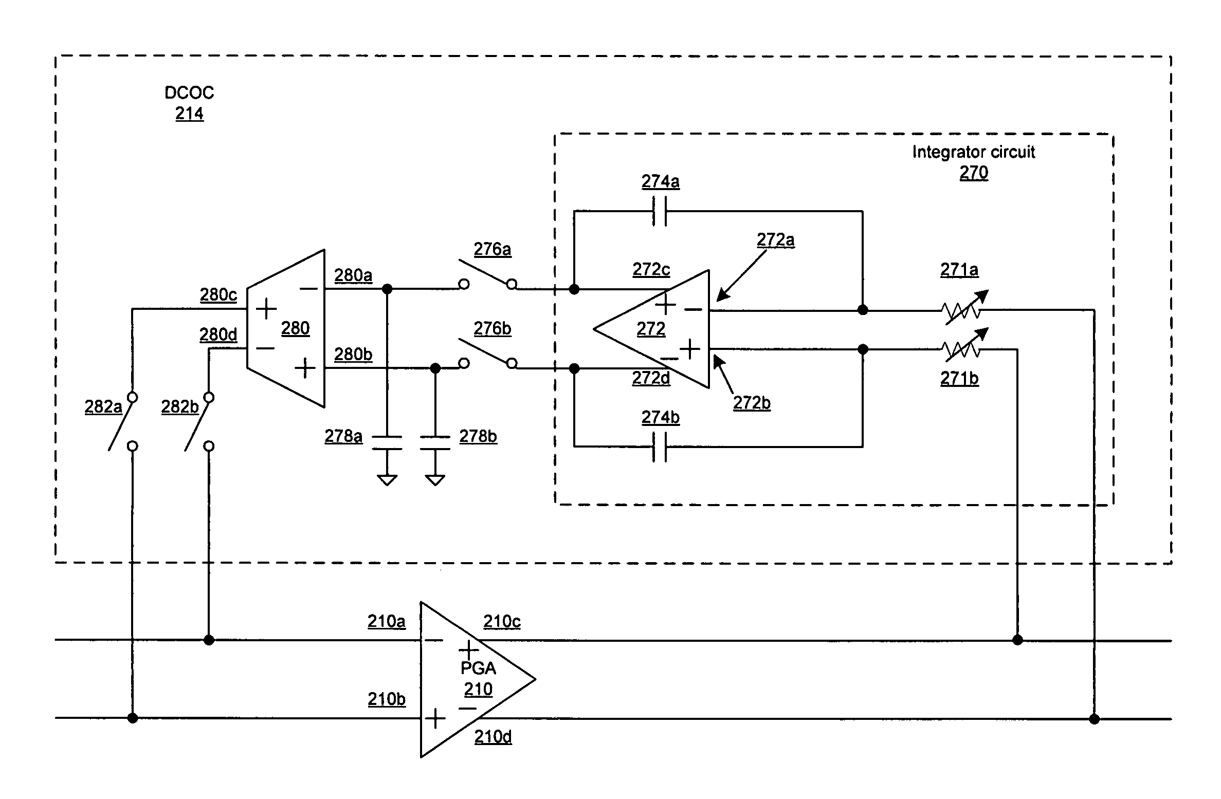
[0028]Certain embodiments of the invention may be found in a method and system for a DC offset correction loop for a mobile digital cellular television environment. Aspects of the method may comprise removing at least a portion of a DC offset from outputs of an amplifier. The DC offset may be removed from a single stage amplifier, or from each stage of a N stage amplifier, where N may be an integer.

[0029]In accordance with various embodiments of the invention, the DC offset may be removed by using second differential signals generated from first differential signals, where the second differential signals may be communicated to inputs of the amplifier. The first differential signals may be generated by a first circuit that integrates outputs of the amplifier using a variable corner frequency that may be adjusted by changing a resistance of at least one variable resistor in the first circuit. The second differential signals may be generated from the first differential signals based on...


PUM


Abstract

Methods and systems for a DC offset correction loop for a mobile digital cellular television environment are disclosed. Aspects of one method may include removing at least a portion of a DC offset from output of an amplifier. The DC offset may be removed from a single stage amplifier, or from each stage of a N stage amplifier, where N may be an integer. The DC offset may be removed by using second differential signals generated from first differential signals, where the second differential signals may be communicated to inputs of the amplifier. The first differential signals may by a first circuit that integrates outputs of the amplifier. The first circuit may perform the integration using a variable corner frequency that may be adjusted by changing a resistance of at least one variable resistor in the first circuit.

Description

CROSS-REFERENCE TO RELATED APPLICATIONS / INCORPORATION BY REFERENCE[0001]This application make reference to, claims priority to, and claims the benefit of:U.S. Provisional Application Ser. No. 60 / 717,915 filed on Sep. 16, 2005; andU.S. Provisional Application Ser. No. 60 / 778,232 filed on Mar. 2, 2006.[0002]This application also makes reference to:U.S. application Ser. No. 11 / 385,390 filed on even date herewith;U.S. application Ser. No. 11 / 385,423 filed on even date herewith;U.S. application Ser. No. 11 / 385,389 filed on even date herewith;U.S. application Ser. No. 11 / 385,401 filed on even date herewith; andU.S. application Ser. No. 11 / 385,081 filed on even date herewith.[0003]Each of the above stated applications is hereby incorporated herein by reference in its entirety.FEDERALLY SPONSORED RESEARCH OR DEVELOPMENT[0004][Not Applicable]MICROFICHE / COPYRIGHT REFERENCE[0005][Not Applicable]FIELD OF THE INVENTION[0006]Certain embodiments of the invention relate to receiver circuitry. More ...

Claims


Application Information

Patent Timeline
Patent Type & Authority Patents(United States)
IPC IPC(8): H03L5/00
CPCH04B1/30
Inventor BOURAS, STAMATIOS ALEXANDROS
Owner AVAGO TECH INT SALES PTE LTD
Learn More