Optimization of vehicular traffic flow through a conflict zone

a technology of conflict zone and traffic flow, applied in the direction of instruments, analogue processes for specific applications, electric/magnetic computing, etc., can solve the problems of existing traffic control and sequencing devices, traffic lights, and inability to allow maximum traffic flow through conflict zones

Inactive Publication Date: 2011-06-28
INT BUSINESS MASCH CORP
View PDF11 Cites 90 Cited by
  • Summary
  • Abstract
  • Description
  • Claims
  • Application Information

AI Technical Summary

Benefits of technology

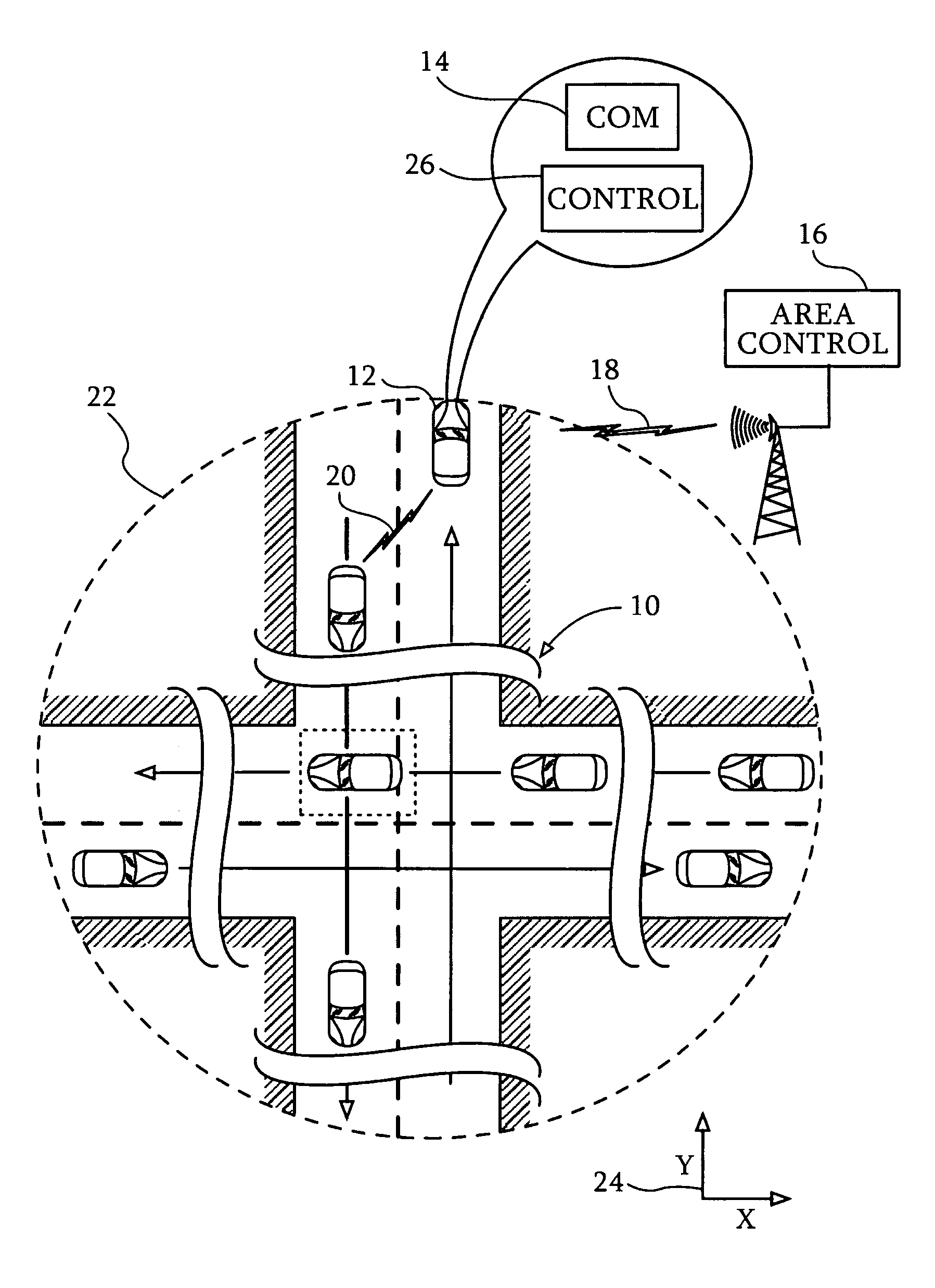
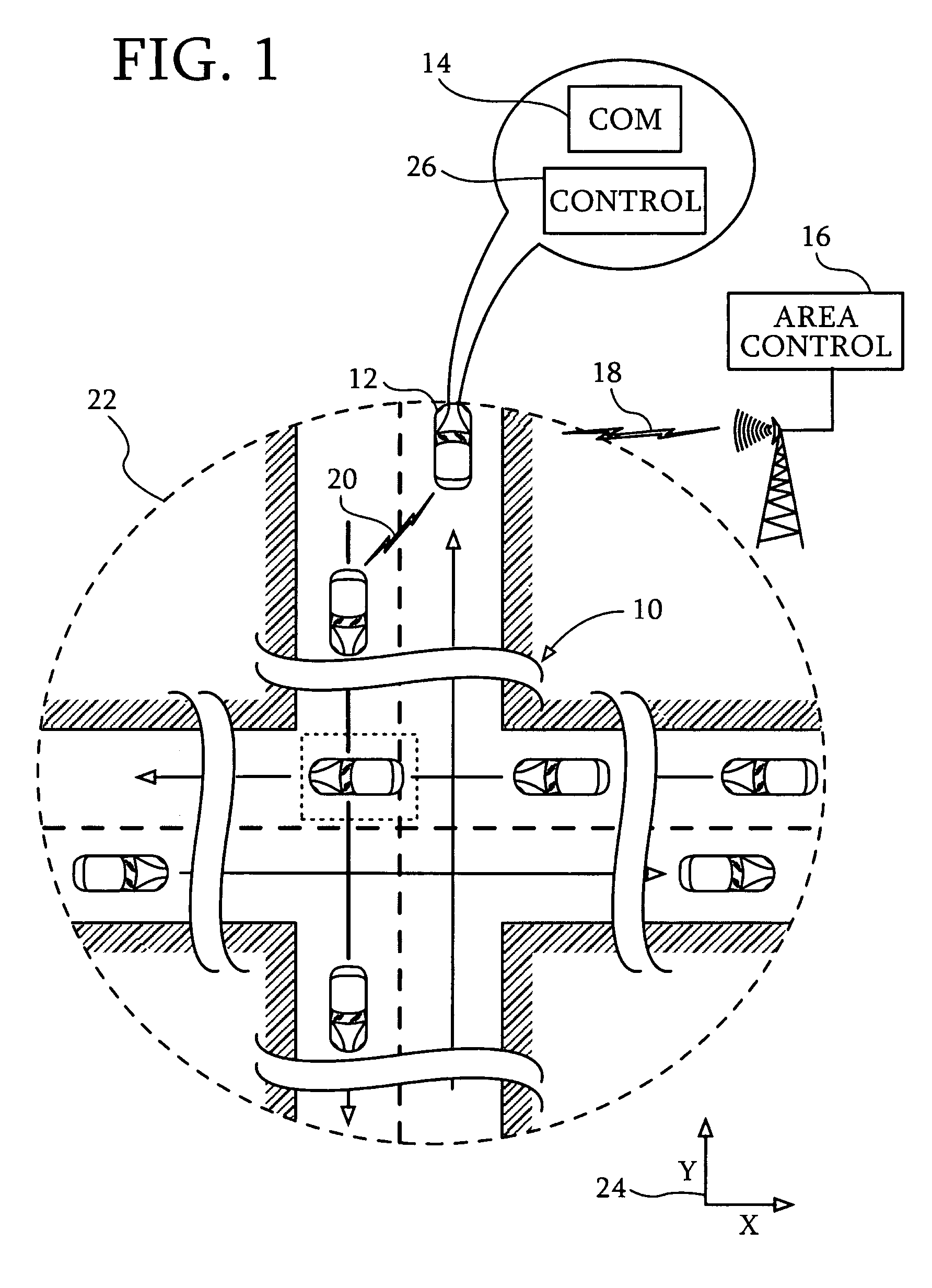
[0008]An embodiment of the invention provides a method of automatic vehicular traffic flow control, which is carried out by defining a controlled area that includes a conflict zone having a plurality of vehicular traffic streams passing therethrough in different directions and entering the controlled area at respective initial speeds. Vehicles belonging to different ones of the vehicular traffic streams contend for occupancy of the conflict zone. The method is further carried out by interleaving the vehicular traffic streams at the conflict zone under automatic control while varying respective zone speeds of the vehicular traffic streams, such that the vehicular traffic streams freely flow through the conflict zone without traffic backup, wherein the zone speeds are not less than the respective initial speeds. Typically, the vehicles are caused to accelerate as they approach the conflict zone in order to increase throughput through the zone.
[0011]One aspect of the method includes preventing the tracking vehicles from entering the conflict zone until their respective tracked vehicles have crossed the conflict zone.

Problems solved by technology

Worsening road traffic congestion has handicapped the quality of life, especially in and around cities.
Such conflict zones are often bottlenecks in traffic flow.
Existing traffic control and sequencing devices, for example traffic lights, do not allow maximum traffic flow through conflict zones, due in part to latencies when changing directions of flow.
It has been suggested that the introduction of computers into vehicles and infrastructure to facilitate traffic flow may help overcome woefully slow response time of humans, but is not intended to replace superior capability of humans to perform complex situation analysis and to make moral judgments.

Method used


Image

  • Optimization of vehicular traffic flow through a conflict zone
  • Optimization of vehicular traffic flow through a conflict zone
  • Optimization of vehicular traffic flow through a conflict zone

Examples


Embodiment Construction

[0034]In the following description, numerous specific details are set forth in order to provide a thorough understanding of the various principles of the present invention. It will be apparent to one skilled in the art, however, that not all these details are necessarily always needed for practicing the present invention. In this instance, well-known circuits, control logic, and the details of computer program instructions for conventional algorithms and processes have not been shown in detail in order not to obscure the general concepts unnecessarily.

[0035]As will be appreciated by one skilled in the art, the present invention may be embodied as a system, method or computer program product. Accordingly, the present invention may take the form of an entirely hardware embodiment, an entirely software embodiment (including firmware, resident software, micro-code, etc.) or an embodiment combining software and hardware aspects that may all generally be referred to herein as a “circuit,”...


PUM


Abstract

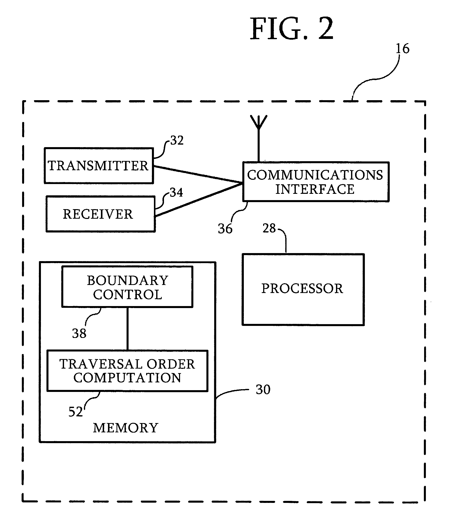
An automatic vehicular traffic flow control technique defines a controlled area, wherein vehicles belonging to different traffic streams contend for occupancy of a conflict zone. A traversal order is computed for the vehicles in the controlled area, wherein the ordered vehicles are assigned to traverse the conflict zone sequentially in accordance with their respective positions in the traversal order. Tracking and tracked vehicles are designated, wherein a respective tracked vehicle immediately precedes each of the tracking vehicles in the traversal order. The tracking vehicles maintain a specified physical relationship with their respective tracked vehicles until the tracked vehicle has traversed the conflict zone. The speed of the traffic streams is increased as necessary so as to achieve a desired throughput through the conflict zone.

Description

BACKGROUND OF THE INVENTION[0001]1. Field of the Invention[0002]This invention relates to vehicular traffic flow control. More particularly, this invention relates to automated control of conflicting streams of vehicular traffic flow that flow through a common zone.[0003]2. Description of the Related Art[0004]Worsening road traffic congestion has handicapped the quality of life, especially in and around cities. This has motivated various attempts at automatic traffic control. Traffic intersections and merge areas are examples of conflict zones, in which forward advance of vehicles is often frustrated by other vehicles vying for the same space. Such conflict zones are often bottlenecks in traffic flow.[0005]Existing traffic control and sequencing devices, for example traffic lights, do not allow maximum traffic flow through conflict zones, due in part to latencies when changing directions of flow.[0006]It has been suggested that the introduction of computers into vehicles and infrast...

Claims


Application Information

Patent Timeline
Patent Type & Authority Patents(United States)
IPC IPC(8): G08B1/00
CPCG08G1/164
Inventor CHEVION, DAN SHMUELRAMM, DOVSHIMONY, YUVALSIVAN, RON
Owner INT BUSINESS MASCH CORP
Why Eureka
Try Eureka