Pixel unit, liquid crystal display panel, electro-optical apparatus, and methods for manufacturing the same

a liquid crystal display and pixel technology, applied in the direction of instruments, vacuum evaporation coatings, coatings, etc., can solve problems such as color shift or color washout, and achieve the effect of improving the display quality of the electro-optical apparatus

Active Publication Date: 2011-06-28
AU OPTRONICS CORP
View PDF9 Cites 4 Cited by
  • Summary
  • Abstract
  • Description
  • Claims
  • Application Information

AI Technical Summary

Benefits of technology

[0010]The present invention is also directed to a liquid crystal display (LCD) panel and a method for manufacturing the same, wherein the problem of color shift is resolved through a simple design.
[0011]The present invention is further directed to an electro-optical apparatus and a method for manufacturing the same, wherein the electro-optical apparatus has high display aperture ratio and simple circuit layout.
[0028]According to the present invention, a UV absorption pattern is disposed in a pixel unit of a LCD panel, so that when a polymer layer is formed in the pixel unit for aligning the liquid crystal molecules, the disposition of the UV absorption pattern allows the polymer layer in different areas to present different states. Thus, in the LCD panel and the pixel unit provided by the present invention, the liquid crystal molecules of a liquid crystal layer can present different pre-tilt angles in different areas, and as a result, the problem of color shift at large viewing angles, for example, an angle substantially greater than or substantially equal to 60° can be resolved. When the LCD panel and the pixel unit in the present invention are applied to an electro-optical apparatus, the display quality of the electro-optical apparatus can be improved.

Problems solved by technology

Thus, when the viewing angle changes, the display brightness presented by the conventional LCD panel also changes, and accordingly the problem of color shift or color washout may be produced.

Method used


Image

  • Pixel unit, liquid crystal display panel, electro-optical apparatus, and methods for manufacturing the same
  • Pixel unit, liquid crystal display panel, electro-optical apparatus, and methods for manufacturing the same
  • Pixel unit, liquid crystal display panel, electro-optical apparatus, and methods for manufacturing the same

Examples


Embodiment Construction

[0038]Reference will now be made in detail to the present preferred embodiments of the invention, examples of which are illustrated in the accompanying drawings. Wherever possible, the same reference numbers are used in the drawings and the description to refer to the same or like parts.

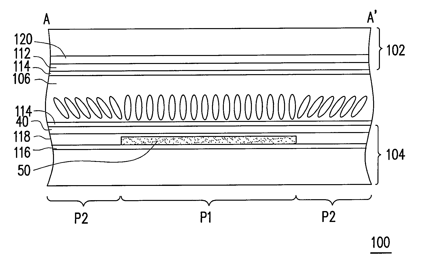
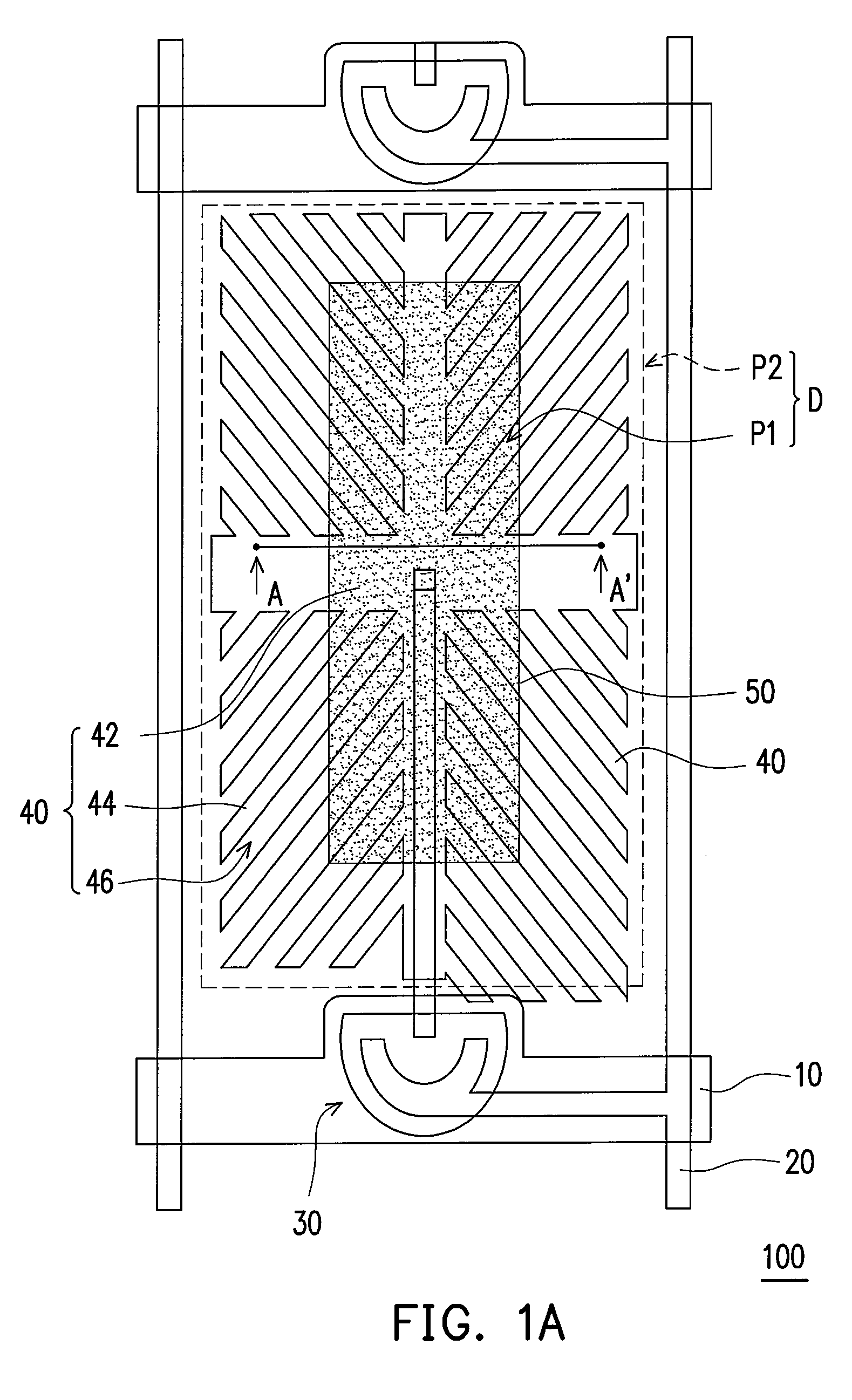
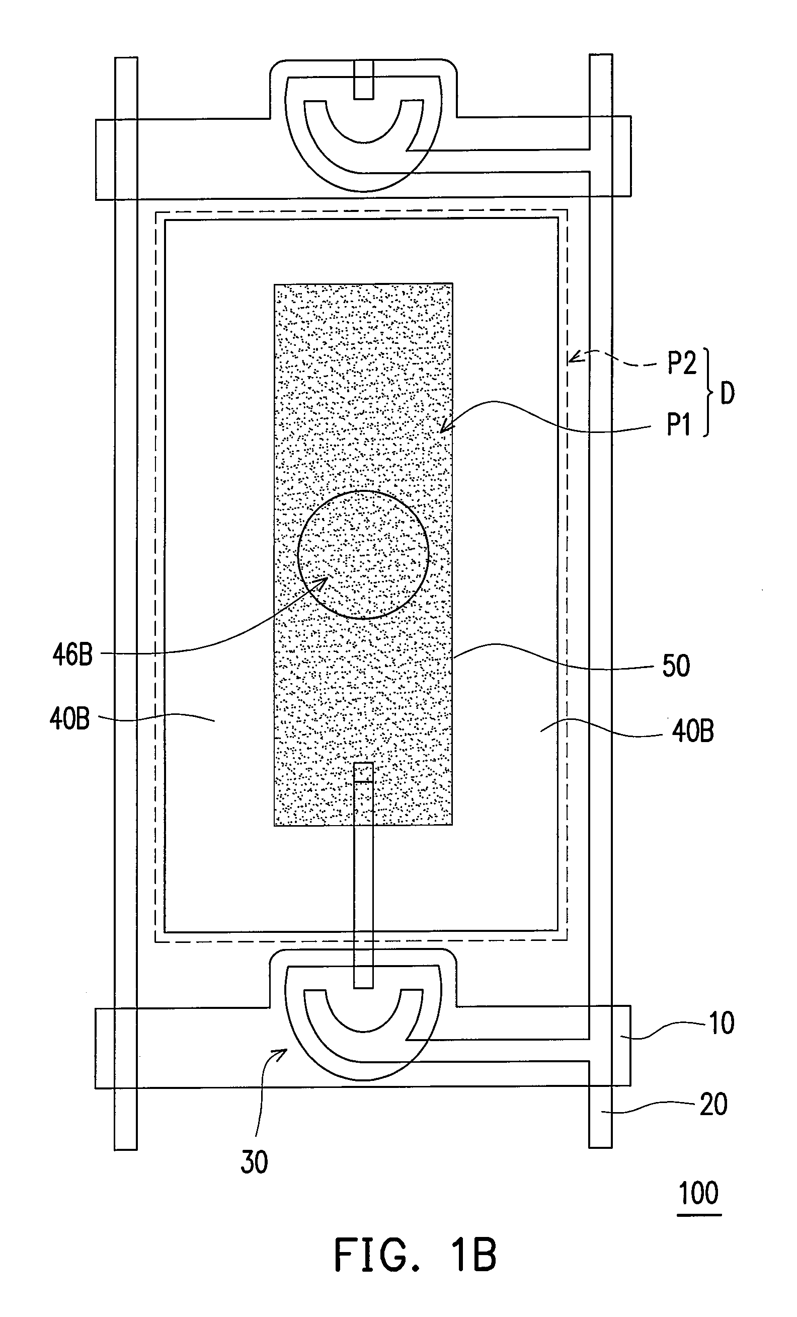
[0039]In order to resolve the problem of color shift at large viewing angles, for example, an angle substantially greater than or substantially equal to 60° presented by a liquid crystal display (LCD) panel, the liquid crystal molecules in a single pixel unit have to be able to present different arrangements so as to present different display brightness. Conventionally, this purpose is achieved through the capacitance coupling effect or by disposing additional transistors. However, by using these conventional methods, the display aperture ratio of the LCD panel is affected and the complexity in driving the LCD panel is increased.

[0040]Accordingly, the present invention provides a pixel unit, wherein ...


PUM

PropertyMeasurementUnit
angleaaaaaaaaaa
angleaaaaaaaaaa
wavelengthaaaaaaaaaa

Abstract

A pixel unit having a display area is provided. The pixel unit includes a first substrate, a second substrate, a liquid crystal layer, and at least one ultraviolet light (UV) absorption pattern. The second substrate is disposed in parallel to the first substrate, and the liquid crystal layer is disposed between the first substrate and the second substrate. The UV absorption pattern is disposed between the first substrate and the second substrate. A part of the display area overlaps the UV absorption pattern to define at least one first alignment area, while the part of the display area which does not overlap the UV absorption pattern defines at least one second alignment area. The liquid crystal molecules of the liquid crystal layer present different pre-tilt angles in the first alignment area and the second alignment area.

Description

CROSS-REFERENCE TO RELATED APPLICATION[0001]This application claims the priority benefit of Taiwan application serial no. 97106634, filed on Feb. 26, 2008. The entirety of the above-mentioned patent application is hereby incorporated by reference herein and made a part of this specification.BACKGROUND OF THE INVENTION[0002]1. Field of the Invention[0003]The present invention generally relates to a pixel unit, a liquid crystal display (LCD) panel, an electro-optical apparatus, and methods for manufacturing the same and, more particularly, to a pixel unit, a LCD panel, and an electro-optical apparatus having wide viewing angle and methods for manufacturing the same.[0004]2. Description of Related Art[0005]Presently, the design of thin film transistor liquid crystal display (TFT-LCD) panel is going toward high contrast ratio, no gray scale inversion, little color shift, high luminance, high color richness, high color saturation, quick response, and wide viewing angle. Techniques for pr...

Claims


Application Information

Patent Timeline
Patent Type & Authority Patents(United States)
IPC IPC(8): G02F1/1335G02F1/1337
CPCG02F1/133788G02F1/133707G02F2201/086G02F2001/133761G02F2001/133757G02F1/133757G02F1/133761
Inventor CHIU, CHUNG-HSIANGLIN, CHING-HUANLIU, SUNG-KAOJENG, YUE-SHIH
Owner AU OPTRONICS CORP
Why Eureka
Try Eureka