Eureka AIR delivers breakthrough ideas for toughest innovation challenges, trusted by R&D personnel around the world.

Disk drive and control method thereof

Inactive Publication Date: 2011-06-28
WESTERN DIGITAL TECH INC
View PDF10 Cites 7 Cited by
  • Summary
  • Abstract
  • Description
  • Claims
  • Application Information

AI Technical Summary

Benefits of technology

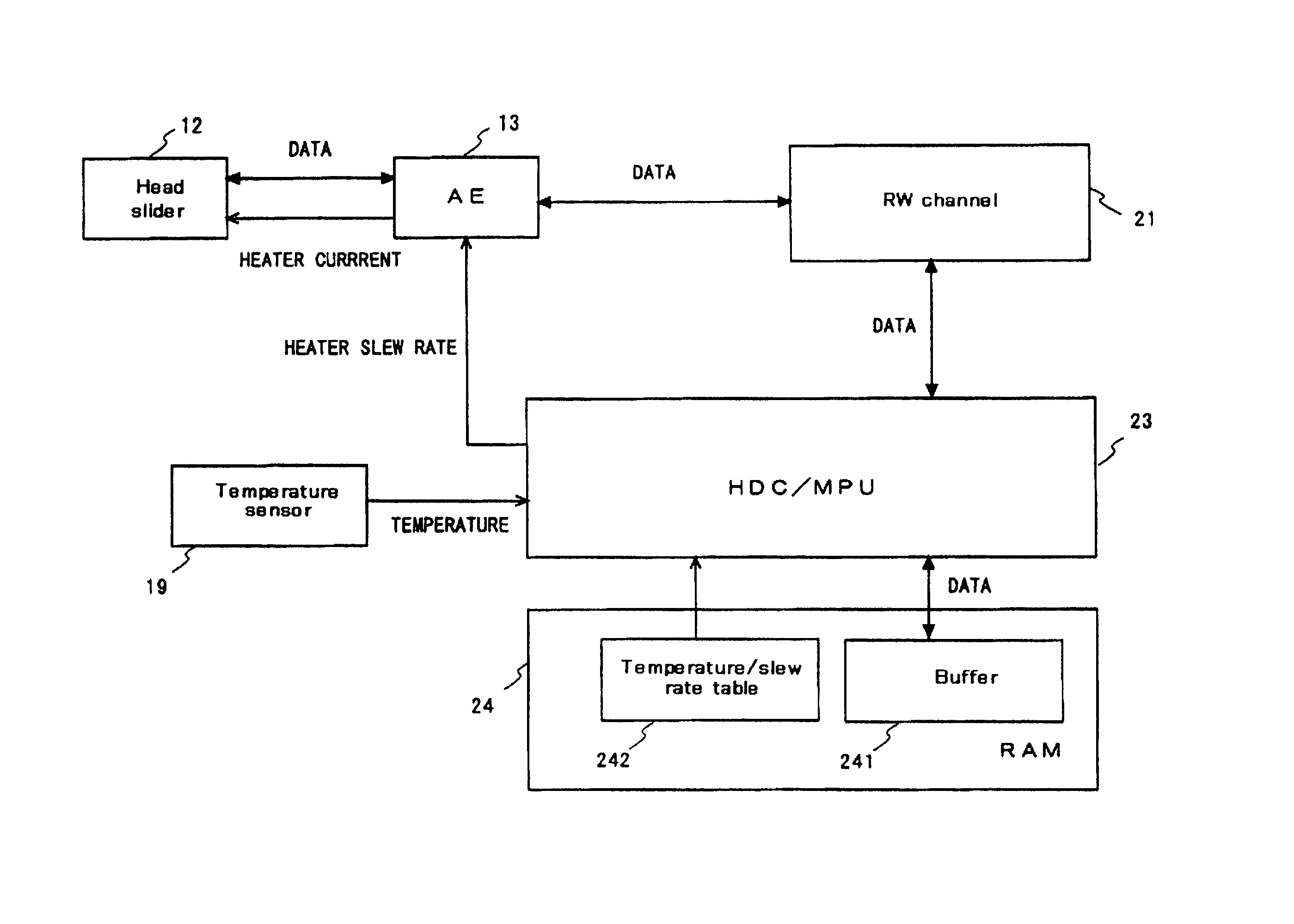
Embodiments in accordance with the present invention reduce the structural stress applied to a head, and achieve the effective control, when the clearance between the head and a disk is adjusted by using a heater. According to the particular embodiment of the present invention shown in FIG. 4, the hard disk controller / microprocessing unit (HDC / MPU) 23 controls a slew rate of a heater at the time of TFC (Thermal Fly height Control). In response to processing conditions, a HDC / MPU 23 changes a slew rate of the output of electric current / voltage applied to the heater. This makes it possible to reduce the head stress, and to achieve the effective TFC. To be more specific, with reference to a temperature / slew rate table 242, the HDC / MPU 23 changes a slew rate in response to the temperature in the read / write processing.

Problems solved by technology

As a result of the study of the inventors, it has been found that if a heater is repeatedly turned ON / OFF by TFC, the structural stress is applied to the heater and the head element, which may cause a device breakdown.
The thermal expansion and thermal shrinkage cause metal fatigue of materials of the heater.
As a result, the breakage of the heater, and a short circuit by electromigration, may occur.
In addition, in the boundary between the heater and a surrounding member thereof, a crack may occur due to the difference in material between them.
In another case, because a read element and a write element repeatedly expand and shrink, a crack occurs in such part, or the electromigration is accelerated.
However, because the useless decrease in slew rate causes the response speed of the clearance adjustment to decrease, it is thought that the intended purpose of the TFC cannot be achieved depending on processing conditions.

Method used


Image

  • Disk drive and control method thereof
  • Disk drive and control method thereof
  • Disk drive and control method thereof

Examples


Embodiment Construction

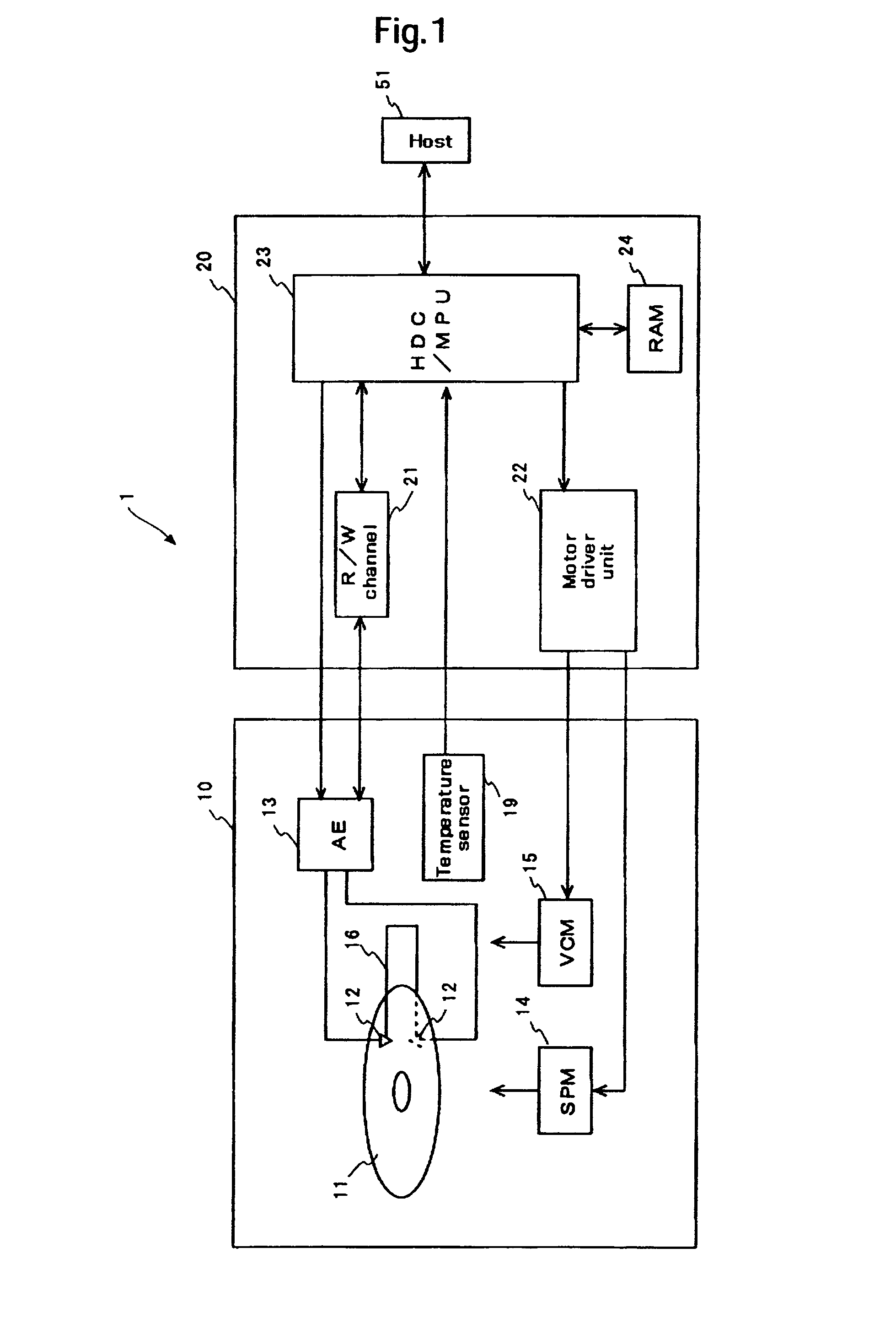
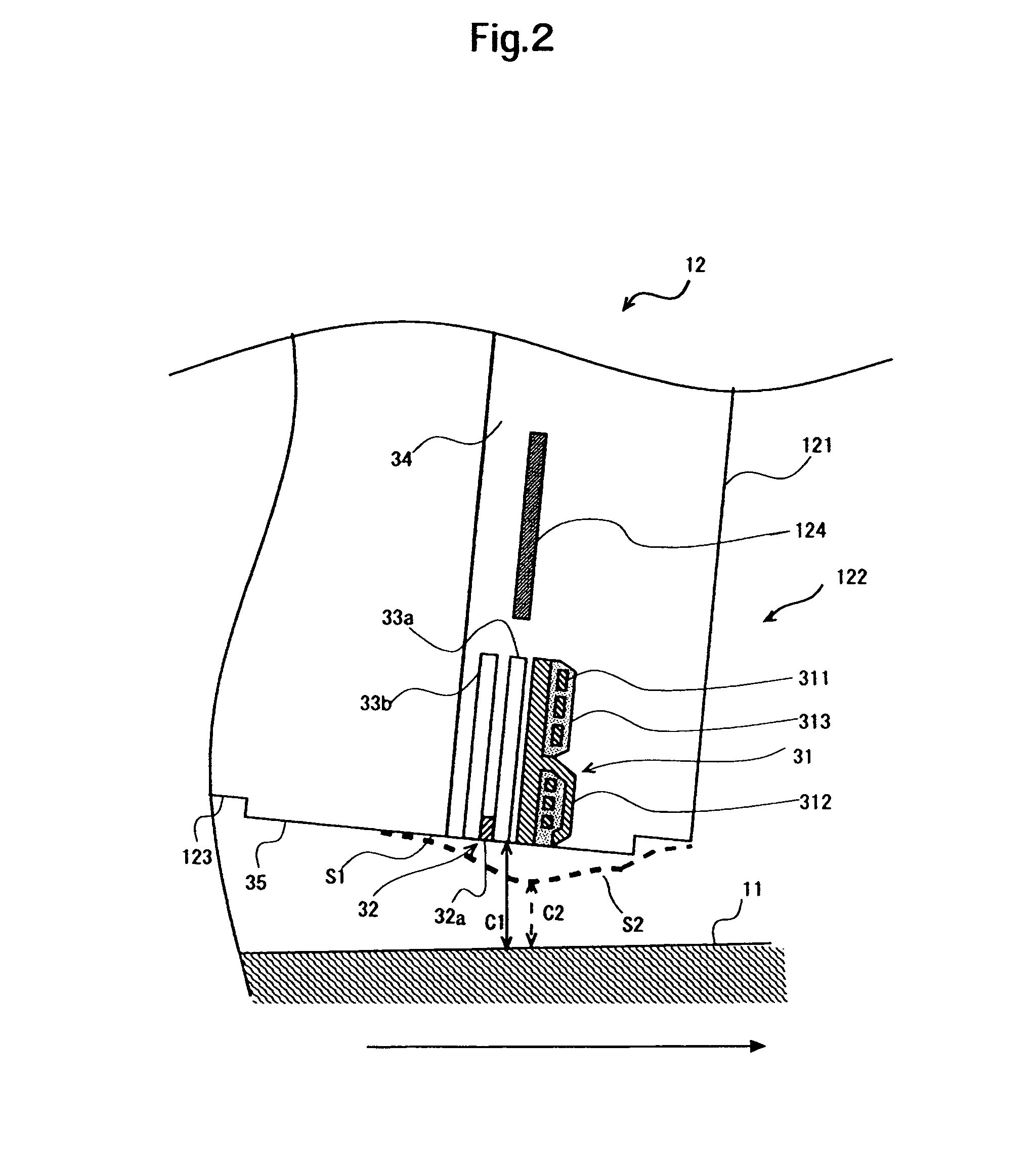
Embodiments in accordance with the present invention relate to a disk drive and a control method thereof, and more particularly to the heater control of a disk drive that is equipped with a heater for adjusting the clearance between a head element and a disk.

According to an embodiment of the present invention, there is provided a disk drive comprising: a slider that flies above a rotating disk; a head element located at the slider; a heater that uses thermal expansion to cause the head element to protrude so that the clearance between the head element and the disk is adjusted, the heater being located at the slider; a controller for determining a slew rate of the output to the heater in response to processing conditions; and a heater driving circuit for driving the heater at the determined slew rate.

Determining the slew rate of the output to the heater in response to the processing conditions, it is possible to reduce the stress applied to the device, and to achieve the effective TF...


PUM


Abstract

Embodiments in accordance with the present invention reduce the structural stress applied to a head, and to achieve the effective control, when the clearance between the head and a disk is adjusted by using a heater. According to one embodiment, the hard disk controller / microprocessing unit (HDC / MPU) controls a slew rate of a heater at the time of TFC (Thermal Fly height Control). In response to processing conditions, a HDC / MPU changes a slew rate of the output of electric current / voltage applied to the heater. This makes it possible to reduce the head stress, and to achieve the effective TFC. To be more specific, with reference to a temperature / slew rate table, the HDC / MPU changes a slew rate in response to the temperature in the read / write processing.

Description

CROSS-REFERENCE TO RELATED APPLICATIONThe instant nonprovisional patent application claims priority to Japanese Patent Application No. 2006-120521 filed Apr. 25, 2006 and incorporated by reference in its entirety herein for all purposes.BACKGROUND OF THE INVENTIONDevices using various types of media such as optical disks, magnetic optical disks, and a flexible magnetic disk are known in the art as disk drives. Among them, hard disk drives (hereinafter referred to as HDDs) have become popular as storage devices for computers to such an extent that they are one of the storage devices indispensable for modern computer systems. Further, not limited to the computers as described above, HDDs are expanding more and more in application due to their excellent properties. For example, HDDs are used for moving picture recording / reproducing devices, car navigation systems, cellular phones, and removable memories for use in digital cameras.A magnetic disk used in the HDD has a plurality of data ...

Claims


Application Information

Patent Timeline
IPC IPC(8): G11B21/02
CPCG11B5/6064G11B5/6005
Inventor SATOH, NORIAKIOHSAWA, TOYOMINAGANO, YUMINISHIYAMA, NOBUMASA
Owner WESTERN DIGITAL TECH INC
Why Eureka
Eureka Blog
Learn More