Semi-plastic sealed permanent magnet synchronous motor

A permanent magnet synchronous motor and component technology, applied in the manufacture of motor generators, electrical components, electromechanical devices, etc., can solve the problems of increasing failure rate, application limitation, unsatisfactory sealing effect, etc., to reduce and vibration noise, The effect of reducing structural stress and good sealing effect

Active Publication Date: 2015-08-12
CHANGZHOU LEILI MOTOR SCI & TECH
View PDF6 Cites 3 Cited by
  • Summary
  • Abstract
  • Description
  • Claims
  • Application Information

AI Technical Summary

Problems solved by technology

[0003] However, the above-mentioned prior art still has great defects. This is because the permanent magnet synchronous motor with the coil assembly of the stator fully enclosed is prone to generate a large amount of heat after a long period of use. No matter the rotor assembly or the energized stator winding assembly, both generate undesired high-temperature heat
However, the adoption of the technical means disclosed in the above-mentioned prior art is extremely unfavorable for the heat dissipation of the motor, or has produced a great negative effect.
Therefore, in the actual use process, due to the poor heat dissipation effect of the above-mentioned motors in the prior art, there are great restrictions on the application occasions or the failure rate is increased.
In order to overcome the problem of heat dissipation of the motor, the prior art CN202260737U also proposes that "a number of heat dissipation holes penetrating the covering body are evenly distributed on the covering body in the rotor assembly". The above technical means have a certain positive effect on heat dissipation, but, Since the heat dissipation hole runs through the cladding body, it is impossible to prevent humid air or dust from corroding the stator or rotor and other components. It is necessary to add other components such as gaskets, which not only increases the cost, but also the sealing effect is not ideal, and the The method cannot be applied to the energized stator winding assembly

Method used


Image

  • Semi-plastic sealed permanent magnet synchronous motor
  • Semi-plastic sealed permanent magnet synchronous motor
  • Semi-plastic sealed permanent magnet synchronous motor

Examples


Embodiment Construction

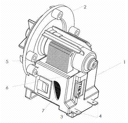
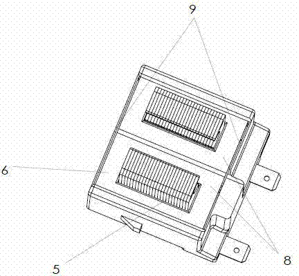
[0024] figure 1 It shows the overall structure of a semi-plastic-encapsulated permanent magnet synchronous motor of the present invention applied in a washing machine. Such as figure 1 As shown, it includes a stator assembly 1, a rotor assembly 2, a thermal protector 3, and an outlet wire insert 4. The stator assembly 1 is composed of a stator core 5, a coil frame 6 and a stator coil winding 7. The rotor assembly 2 includes The permanent magnet rotor located inside the pump body ( figure 1 not shown), the magnetic field generated after the stator coil winding 7 is energized drives the permanent magnet rotor to rotate, thereby driving the impeller coaxially arranged with the permanent magnet rotor to rotate, thereby realizing functions such as water supply or drainage. The stator assembly 1 is fixedly installed on the pump body of the rotor assembly 2 through the coil frame 6, the stator coil winding 7 is wound on the coil frame 6, the stator coil winding 7 is connected to th...


PUM


Abstract

The invention relates to a semi-plastic-package permanent-magnet synchronous motor including a stator assembly (1), a rotor assembly (2), a heat protector (3) and a lead-out wire inserting sheet (4). The stator assembly is composed of a stator iron core (5), a coil frame (6) and a stator coil winding (7). The stator coil winding (7) is coiled on the coil frame (6). The stator coil winding (7) is connected with the heat protector (3). The heat protector (3) is connected with the lead-out wire inserting sheet (4). Connection positions of the heat protector (3), the stator coil winding (7), the heat protector (3) and the lead-out wire inserting sheet (4) are completely plastic-packaged in resin material on the coil frame (6). At least one part of a rest part of the coil frame (6) has an exposed surface and is not plastic-packaged by the resin material. Therefore, the semi-plastic-package permanent-magnet synchronous motor can be prevented from oxidation and corrosion and can have a good heat dissipation effect.

Description

technical field [0001] The invention relates to a semi-plastic-enclosed permanent magnet synchronous motor, in particular to a semi-plastic-enclosed permanent-magnet synchronous motor used in household appliances such as washing machines. Background technique [0002] At present, the permanent magnet synchronous motors for household appliances disclosed in the market and related prior art are mainly composed of stator components, rotor components, thermal protectors and other related wiring components. Since the motor is often faced with a humid working environment, and the energized stator coil is easy to absorb a large amount of dust and other sundries, the working environment faced by the motor is relatively harsh. Therefore, in order to prevent the motor from being corroded or oxidized, it is usually necessary to seal the relevant wiring components such as the stator assembly, the rotor assembly, and the thermal protector with plastic sealing to isolate them from the har...

Claims


Application Information

Patent Timeline
Patent Type & Authority Patents(China)
IPC IPC(8): H02K3/44H02K3/38H02K1/20H02K15/00
Inventor 王胜赵殿合邵韦
Owner CHANGZHOU LEILI MOTOR SCI & TECH
Why Eureka
Try Eureka