Compound tooling system for molding applications

a technology of molding applications and tooling systems, which is applied in the field of compound molding units to achieve the effects of good natural release qualities, high heat resistance, and flexibility of the elastomer or polymer used

Active Publication Date: 2011-07-05
ODONOGHUE JOSEPH
View PDF40 Cites 110 Cited by
  • Summary
  • Abstract
  • Description
  • Claims
  • Application Information

AI Technical Summary

Benefits of technology

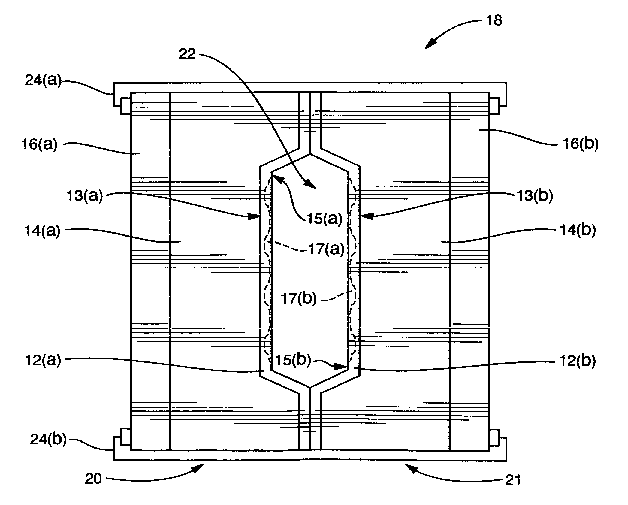
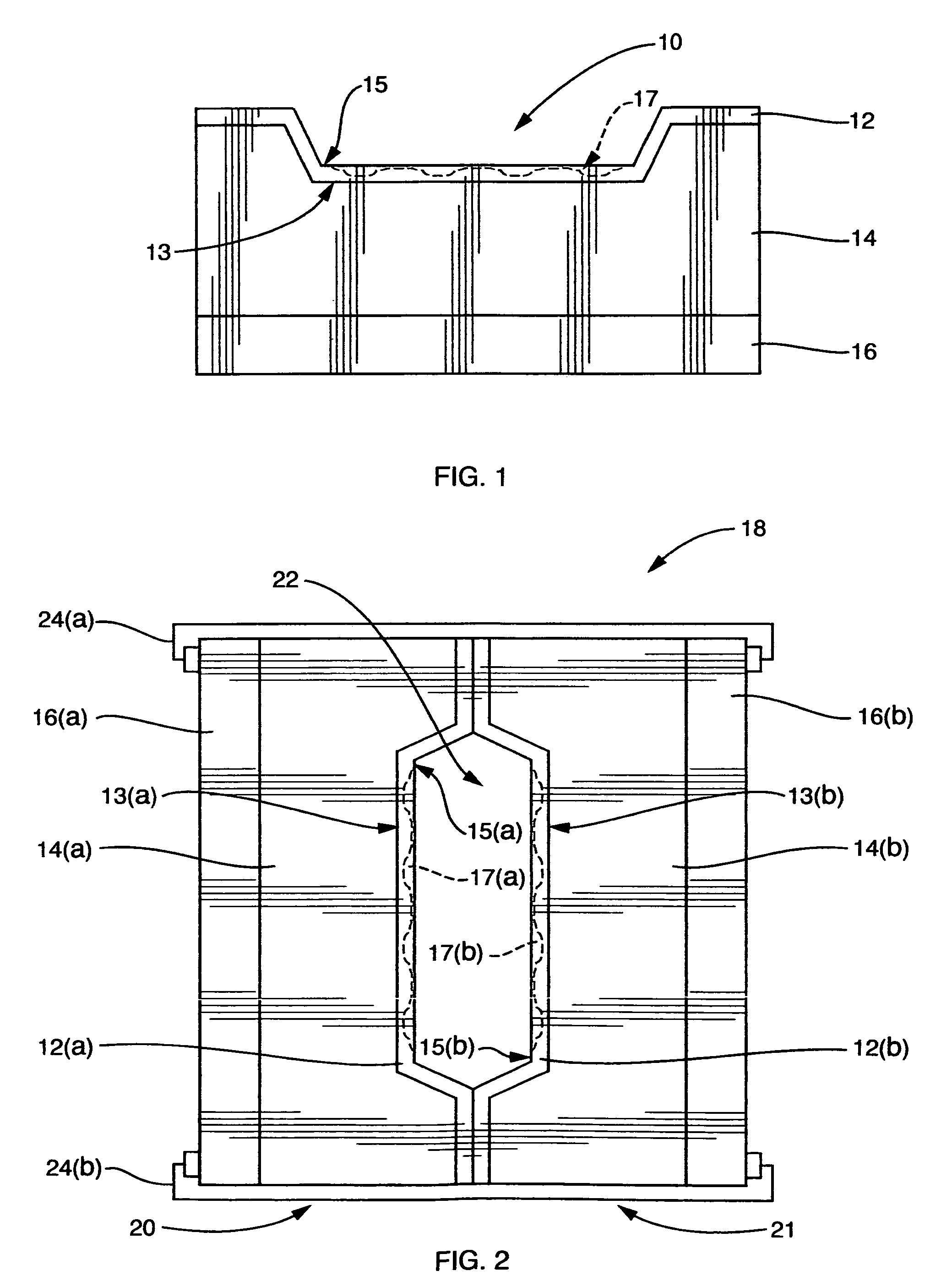
[0018]The standard tooling unit of the system consists of three parts, the backing-plate, the backing-mold and the skin-mold. This is true regardless of whether the mold as a whole is one-, two-, or multi-part, and each mold according to the invention will, therefore, comprise one or more of these standard tooling units. The typical elastomeric compound mold consists of an elastomer skin-mold temporarily bonded to, and supported by a backing-mold and a rigid backing-plate. The backing-mold and the rigid backing-plate provide both general and local support, as well as rigidity, to the flexible skin which provides the final shape and surface finish to the compound mold. Bonding is preferably effected by vacuum acting through the backing-mold on the rear surface of the skin-mold. The typical closed-mold unit consists of the skin-mold halves bonded to, and sandwiched between, two backing-molds which are clamped together under adequate compression to seal the mold against filling pressures.
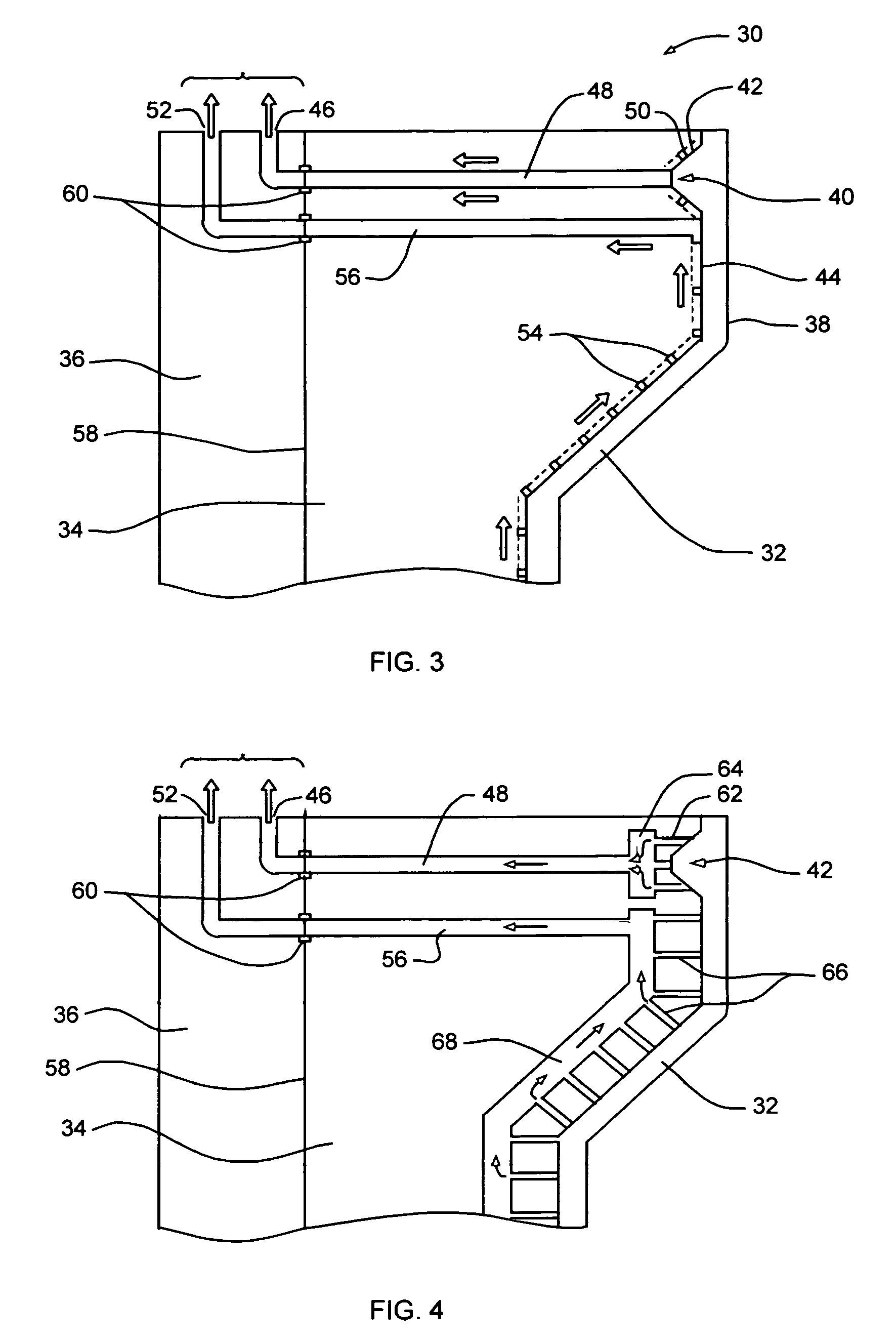
[0026]Because the backing-mold is highly conformal to the skin-mold, so too are these systems and they may be easily modified according to part wall thickness and other factors. System lines may be focused or dispersed to suit the part geometry and any system may be broken up into a number of systems within the backing-mold each connecting to the system ports or to a manifold molded into the backing-mold and connecting to the ports. For large molds, in particular, such a system may allow more even heating or cooling and a more rapid response to fluid temperature changes. Such systems may also be designed to control heating or cooling, both temporally and spatially or directionally, to allow greater control on curing and solidification. Such control may allow complex part geometries to be molded while conferring the ability to neutralize or reduce the associated stresses typical of such parts.
[0032]Matching mold cavity alignment is maintained by a key and key-way system consisting of individual keys placed selectively around each mold cavity and elsewhere over the surface of the mold halves, as necessary. Accurate lateral alignment between the skin-mold and each backing-mold is accomplished by placing a reflecting key\key-way system at the interface with additional keys behind each cavity, where key location is less selective. A large continuous key-way\seal is placed around the mold perimeter to aid in coarse skin-mold alignment and, under compression, to seal the mold against the vacuum-evacuation or injection pressures, the seal being modified at the mold ports depending on the molding process used. This perimeter key-way\seal is reflected, and is fully continuous, in both skin-mold\backing-mold interfaces to seal each interface against the bonding vacuum which holds the skin-molds in place.

Problems solved by technology

The rigid polymer skin-mold may be mechanically fastened to the backing-mold as its rigidity will preclude an adequate vacuum seal.

Method used


Image

  • Compound tooling system for molding applications
  • Compound tooling system for molding applications
  • Compound tooling system for molding applications

Examples


Embodiment Construction

[0045]In a tooling system according to the invention, the standard mold unit, or mold half in the case of matched molds, consists of a three-piece compound mold, the backing-plate, the backing-mold and the skin-mold.

[0046]The backing-plate is preferably one of a standard menu of backing-plates of various sizes and shapes suited to various sizes and shapes of molds depending on the general size and geometry of the part to be molded and carries standard features such as mold clamping systems, process connections, and the like. The backing-plate is designed to be rigid enough to withstand all molding and clamping pressures etc., its design also including whatever is required to integrate the mold into the molding process used, except actual cavity filling systems.

[0047]The backing-mold is a conforming section which mates with the backing-plate according to a standard system of guide pins or keys and is mechanically attached by any suitable means. The backing-mold may be solid, syntacti...


PUM

PropertyMeasurementUnit
pressureaaaaaaaaaa
perimeteraaaaaaaaaa
lengthaaaaaaaaaa

Abstract

A compound mold or tooling system is designed to provide an alternative to conventional, expensive, metal molds for various plastics molding applications. The compound mold comprises a replaceable thin-walled liner, or skin-mold, defining the mold surface, temporarily bonded by vacuum means or mechanical means to a conforming backing-mold mold body supported by a rigid backing-plate. Both skin- and backing-molds are composed of suitable polymers with or without additives, fillers, reinforcements or other inclusions depending on mold requirements. The backing-plate contains standard features and fixtures common to all molds used in the particular process or of a particular geometry.

Description

[0001]This application claims priority from provisional application for patent No. 60 / 717,362 filed on Sep. 16, 2005.FIELD OF THE INVENTION[0002]The invention concerns compound tooling systems for molding applications, and more particularly discloses a compound mold unit for use in plastics molding applications, and methods for using such mold unit.BACKGROUND OF THE INVENTION[0003]Conventional molding methods, particularly methods for injection molding of thermoplastics, generally involve the cycling of a single, usually expensive, hard, permanent mold very rapidly in conjunction with expensive molding equipment. Molds are usually made of steel or other metal alloys and are designed and economical only for large production runs. The high cost of mold production, as well as the high molding pressures used, impose size constraints on the mold and hence the size of the part which can be produced.[0004]Thermosetting liquid resin injection or transfer molding methods generally use lower ...

Claims


Application Information

Patent Timeline
Patent Type & Authority Patents(United States)
IPC IPC(8): B29C39/00
CPCB29C33/40B29C33/565B33Y80/00
Inventor O'DONOGHUE, JOSEPH
Owner ODONOGHUE JOSEPH
Why Eureka
Try Eureka