
Non-conductive balloons and methods of producing same

a technology of non-conductive balloons and balloons, which is applied in the field of non-conductive balloons, can solve the problems of reducing the barrier properties of the film and subsequently the inflated life of the balloon, microscopic cracks in the metalized layer, and the difference in mechanical properties between the nylon layer and the metalized layer, etc., and achieves low electrical conductivity and low electrical conductivity. , the effect of improving the adhesion

Active Publication Date: 2011-07-05
ANAGRAM INT INC
View PDF14 Cites 11 Cited by
  • Summary
  • Abstract
  • Description
  • Claims
  • Application Information

AI Technical Summary

Benefits of technology

"The present invention is about making non-latex balloons that have low electrical conductivity. This is achieved by using a metalized layer that is sandwiched between an elastomeric sealant layer and a film layer. Alternatively, a primer can be used to improve adhesion between the layers. The balloons made using this method have low electrical conductivity, increased float life, improved scuff resistance, and the necessary strength to manufacture non-latex balloons. The invention is useful for situations where electrical conductivity needs to be minimized, such as for use in electrical insulation or in situations where static charge can be a problem."

Problems solved by technology

However, the difference in mechanical properties between the Nylon layer and metalized layer can be problematic in this application.
Upon inflation of a balloon, the Nylon layer stretches and can cause microscopic cracks in the metalized layer because the metalized layer does not have the same elastic properties as the Nylon.
This unfortunately reduces the barrier properties of the film and subsequently the inflated life of the balloon.
However, when a more stretch resistant film is utilized in a helium balloon construction this often results in greater instances in seam failure and film cracking because the force that was being dissipated by the film is now more highly concentrated at other areas of the balloon.
The metal layer has been the focus of unsupported claims that buoyant metalized helium balloons have become entangled in power lines leading to nuisance power outages.

Method used


Image

  • Non-conductive balloons and methods of producing same
  • Non-conductive balloons and methods of producing same

Examples


examples

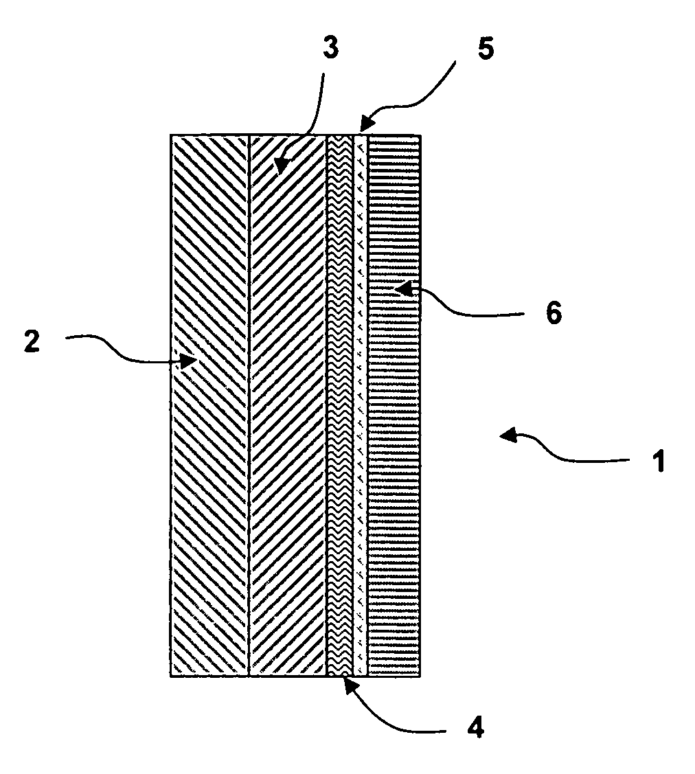
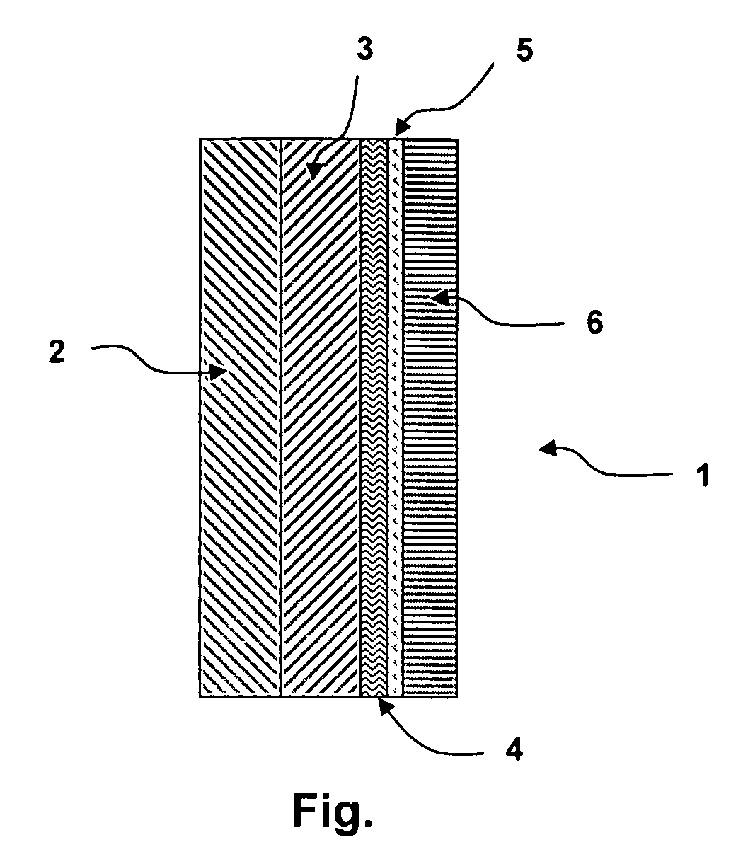
[0030]Several tests were performed to evaluate balloons made using the methods and films of this invention. The first test involved a side by side experiment comparing control balloon products to balloon products made with the film of this invention. The following balloon compositions were tested:[0031]1) Control—a film comprising a metalized layer / a PET layer / an amorphous PET layer / a primer layer / an extrusion coated sealant layer[0032]2) Hurst '588 patent—a film comprising a non-elastomeric sealant layer / a metalized layer / non-elastomeric polyester layer (col. 6, lines 34-45).[0033]3) Present Invention—a film comprising a PET layer / an amorphous PET layer / a metalized layer / an extrusion coated elastomeric sealant layer.[0034]4) Present Invention—a film comprising a PET layer / an amorphous PET layer / a metalized layer / a primer layer / an extrusion coated elastomeric sealant layer.[0035]5) Present Invention—a film comprising an amorphous PET layer / a PET layer / a metalized layer / an extrusion ...


PUM

PropertyMeasurementUnit
pressureaaaaaaaaaa
thicknessaaaaaaaaaa
elongationaaaaaaaaaa

Abstract

The present invention relates to articles and methods for producing non-latex balloons with low surface electrical conductivities and an extended product life. In a preferred embodiment, a multilayer composite film having an exposed metallized layer is coated with an elastomeric sealant layer that increases electrical resistivity of the balloon product to greater than 1.08 Ohms / sq. The invention relates to articles and methods for producing needed bonds and seal strength required to manufacture non latex balloons. The balloons of this invention have an extended product life because they are more resistant to common defects like pin holing and stress cracks than conventional balloon systems.

Description

SUMMARY OF THE INVENTION[0001]The present invention relates to non-latex balloons having low electrical conductivity and to methods for producing such balloons, where at least one metalized layer is encapsulated with an elastomeric film layer. The low electrical conductivity is achieved by providing a balloon construction wherein a metalized layer is sandwiched between an elastomeric sealant layer and a film layer. Alternatively, our invention incorporates a primer that improves the adhesion between the elastomeric sealant and metalized layers. The balloons of these embodiments have low electrical conductivity, increased float life, improved scuff resistance and the needed bonds and seal strength required to manufacture non latex balloons.[0002]For the purpose of this invention electrical conductivity is a measure of how well the surface of the balloon accommodates the movement of an electric charge. Electrical resistivity is the reciprocal of conductivity. It is the opposition to t...

Claims


Application Information

Patent Timeline
Patent Type & Authority Patents(United States)
IPC IPC(8): A63H3/06B31B50/64
CPCA63H27/10B32B1/00B64B1/14B64B1/40B32B27/06A63H2027/1025Y10T156/1052B32B15/08B32B27/08B32B27/32B32B27/34B32B27/36B32B2250/05B32B2255/10B32B2255/205B32B2307/20B32B2307/702B32B2307/72
Inventor SARNSTROM, TODDANSOLABEHERE, PAULBORCHARDT, DEANSWANSON, ANDREWCERNOHOUS, JEFFREY J.FATICA, MICHAELCHICARELLA, GIANFRANCO
Owner ANAGRAM INT INC
Learn More