
Method and apparatus for real time dosimetry

a technology of real-time dosimetry and apparatus, applied in the field of method and apparatus for real-time dosimetry, can solve problems such as confusion in the deduced location of sources

Inactive Publication Date: 2011-07-05
UNIV OF WOLLONGONG
View PDF9 Cites 2 Cited by
  • Summary
  • Abstract
  • Description
  • Claims
  • Application Information

AI Technical Summary

Benefits of technology

This approach provides accurate, real-time monitoring of radiation doses, reducing the risk of complications by ensuring precise placement of radioactive seeds and minimizing exposure to healthy tissues, thereby improving the effectiveness and safety of prostate brachytherapy treatments.

Problems solved by technology

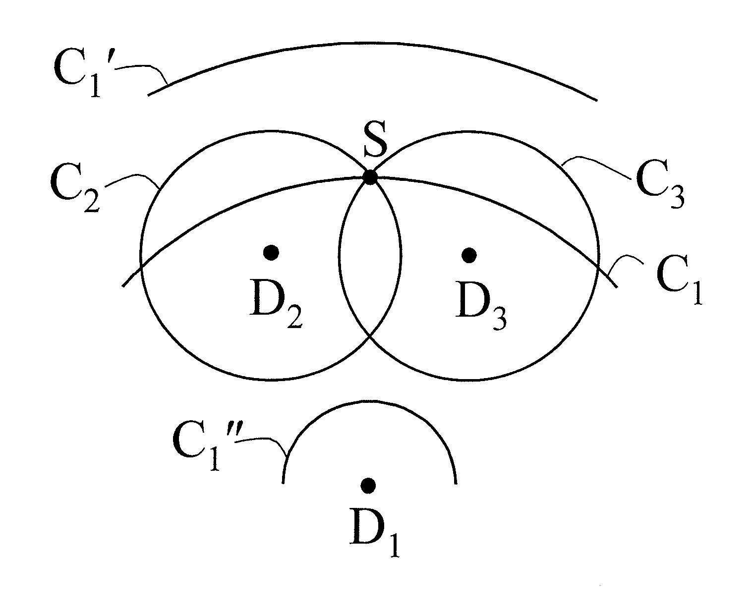
With three detectors, in some cases ambiguity may arise in the deduced location of the source.

Method used


Image

  • Method and apparatus for real time dosimetry
  • Method and apparatus for real time dosimetry
  • Method and apparatus for real time dosimetry

Examples


Embodiment Construction

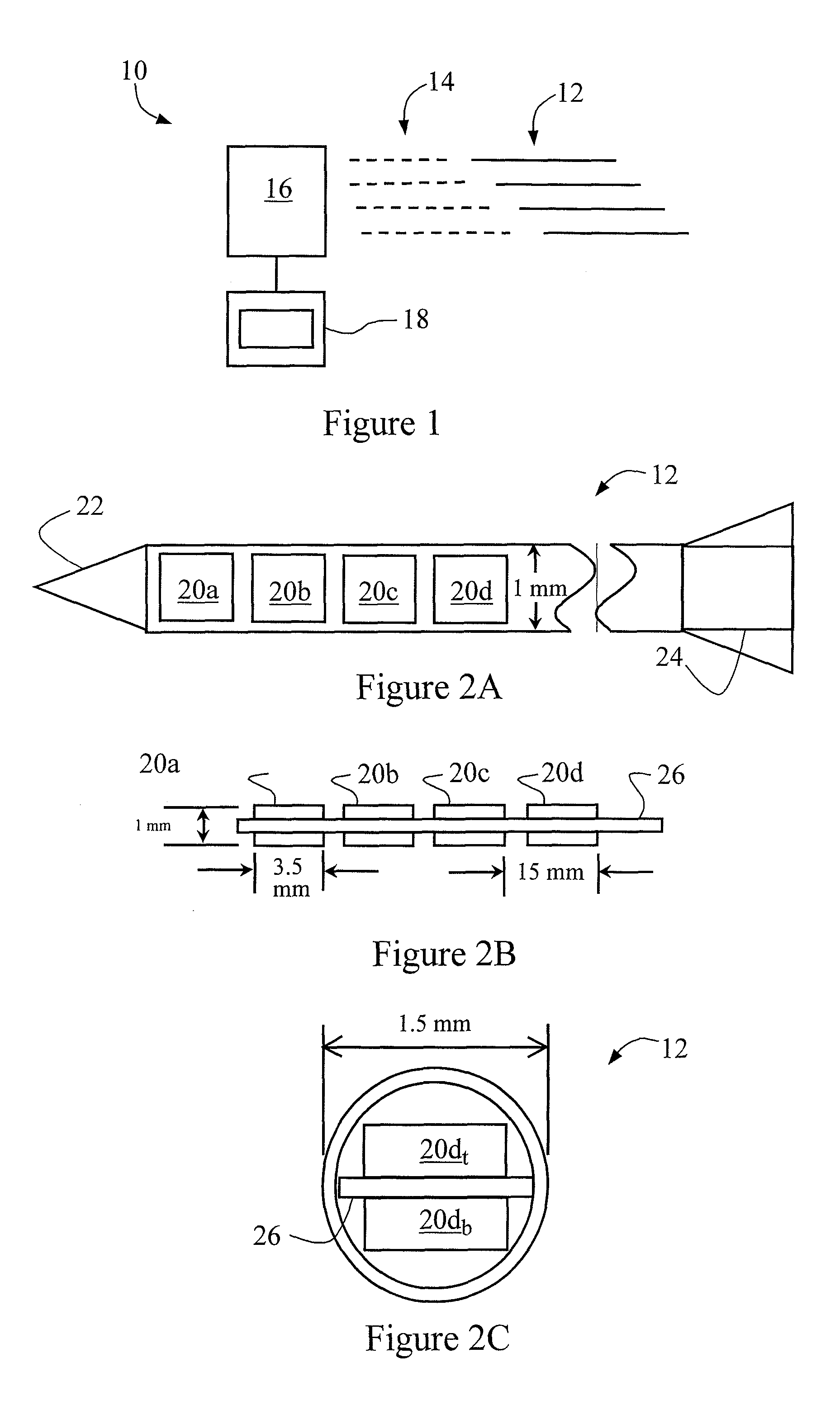
[0083]In an embodiment of the present invention, there is provided a system for determining the dose rate of a radiation source in vivo during brachytherapy, shown schematically at 10 in FIG. 1.

[0084]The system 10 includes four, essentially identical probes in the form of plastic needles 12, connected optically 14 to data collection unit 16. The collection unit 16 is connected to dose-planning and control computer 18, for processing data and producing the final results.

[0085]FIG. 2A is a partial top view of a needle 12, in cross section. Each needle 12 has an internal diameter of 1.5 mm, and contains four silicon PIN diode, CdZnTe or scintillator detectors 20a, 20b, 20c and 20d near the head 22 of the needle 12. The detectors 20a, 20b, 20c and 20d thus occupy only a small forward portion of the total length of the needle 12, which may be between 20 and 30 cm in length.

[0086]The tail 24 of the needle 12 contains the detector electronics for the detectors 20a, 20b, 20c and 20d.

[0087]...


PUM


Abstract

A method of determining the dose rate of a radiation source includes locating three or more detectors in the vicinity of the source. Each detector provides an output indicative of the amount of radiation received from the source and determining the location of the source from at least three of the detector outputs, wherein as many of the detector outputs is required to provide an acceptably accurate result are used in determining the location. Thus, the dose of radiation from the source can be determined from the determined location of the source and either a known activity of the source or a measure of the activity of the source determined by means of the detectors.

Description

CROSS REFERENCE TO RELATED APPLICATIONS[0001]This application is a continuation of U.S. patent application Ser. No. 10 / 350,357, filed on Jan. 24, 2003, now U.S. Pat. No. 7,361,134, and claims benefit of U.S. provisional application No. 60 / 350,951, filed on 25 Jan. 2002.FIELD OF THE INVENTION[0002]The present invention relates to a method and apparatus for real time dosimetry, and is of particular but by not exclusive application in the monitoring of the radiation dose during the placement of one or more radiation sources, and for adjusting the placement of subsequent radiation sources on the basis of the results of such dosimetry.BACKGROUND OF THE INVENTION[0003]With the increasing age and survival of males in the western world and the early diagnosis of prostate cancer, due to the availability of screening (such as PSA screening), prostate cancer has become one of the most commonly diagnosed tumours in the western world. More recently, there has been a large swing away from radical...

Claims


Application Information

Patent Timeline
Patent Type & Authority Patents(United States)
IPC IPC(8): A61N5/00A61N5/10
CPCA61N5/1007A61N5/1027A61N5/1048A61N2005/1072A61N5/1071
Inventor ROZENFELD, ANATOLYZAIDER, MARC
Owner UNIV OF WOLLONGONG
Learn More