Outside plant telecommunications cabinet direct air cooling system

a technology for telecommunications cabinets and outside plants, which is applied in the field of cabinets, can solve the problems of consuming space within the enclosure, bulky air conditioning units and heat exchanger units, and adding weight to the enclosure, so as to improve the air flow direction, improve the air flow density, and compact overall size

Active Publication Date: 2011-07-05
COMMSCOPE INC
View PDF20 Cites 34 Cited by
  • Summary
  • Abstract
  • Description
  • Claims
  • Application Information

AI Technical Summary

Benefits of technology

[0014]The Applicants have also appreciated that the radiant heating of the cabinet could be greatly improved by a system to cool one or more of the outer walls of the cabinet.
[0016]The Applicants have also appreciated a need in the art for a cabinet which improves on one or more of the following attributes: (A) minimization of acoustic noise from active components within the cabinet (such as fans); (B) a more compact overall size and increased density of electronic equipment within the housing; (C) a more streamlined outer housing shell; (D) a better directing of air flow to optimize the cooling effects within the cabinet; (E) a heating system for maintaining the interior of the enclosure above a prescribed temperature; (F) a fan redundancy to ensure performance in the case of a fan failure; (G) a variable speed fan system to prolong the lifespan of a filtering membrane; and / or (H) a monitoring system for reporting a potentially clogged membrane to a remote location.
[0017]The Applicants have also appreciated a need for a cabinet which is simple in design, rugged, more flexible as to end uses, easy to manufacture and / or less expensive to manufacture.

Problems solved by technology

With the cabinets of the prior art, air conditioning units and heat exchanger units are bulky, add weight to the enclosure, and consume space within the enclosure.

Method used


Image

  • Outside plant telecommunications cabinet direct air cooling system
  • Outside plant telecommunications cabinet direct air cooling system
  • Outside plant telecommunications cabinet direct air cooling system

Examples


Embodiment Construction

[0030]The present invention now is described more fully hereinafter with reference to the accompanying drawings, in which embodiments of the invention are shown. This invention may, however, be embodied in many different forms and should not be construed as limited to the embodiments set forth herein; rather, these embodiments are provided so that this disclosure will be thorough and complete, and will fully convey the scope of the invention to those skilled in the art.

[0031]Like numbers refer to like elements throughout. In the figures, the thickness of certain lines, layers, components, elements or features may be exaggerated for clarity. Broken lines illustrate optional features or operations unless specified otherwise.

[0032]The terminology used herein is for the purpose of describing particular embodiments only and is not intended to be limiting of the invention. Unless otherwise defined, all terms (including technical and scientific terms) used herein have the same meaning as c...


PUM


Abstract

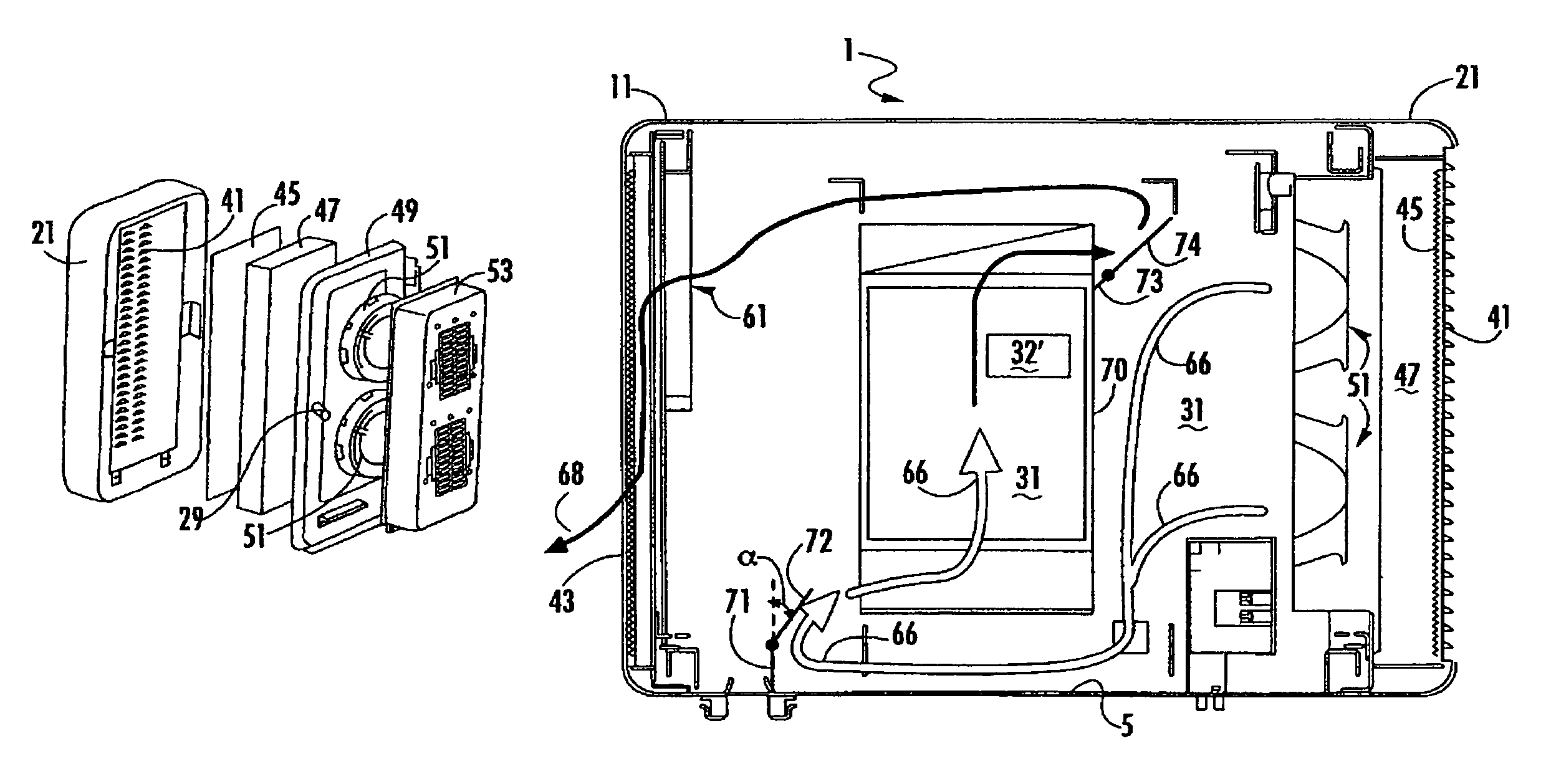
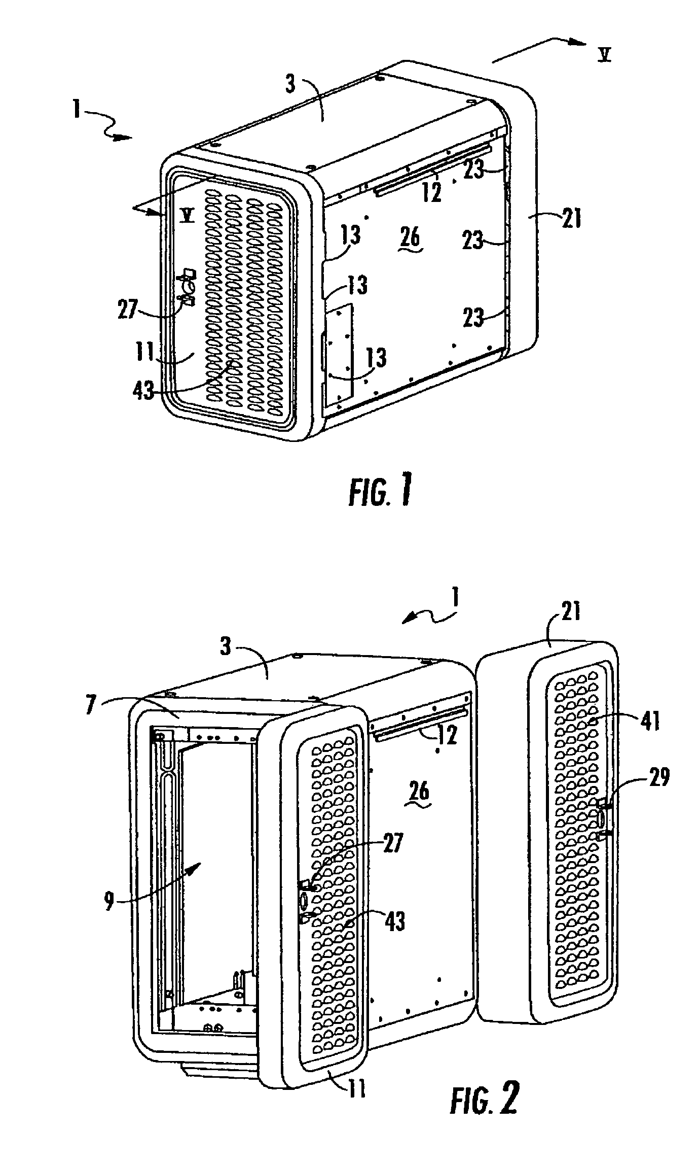
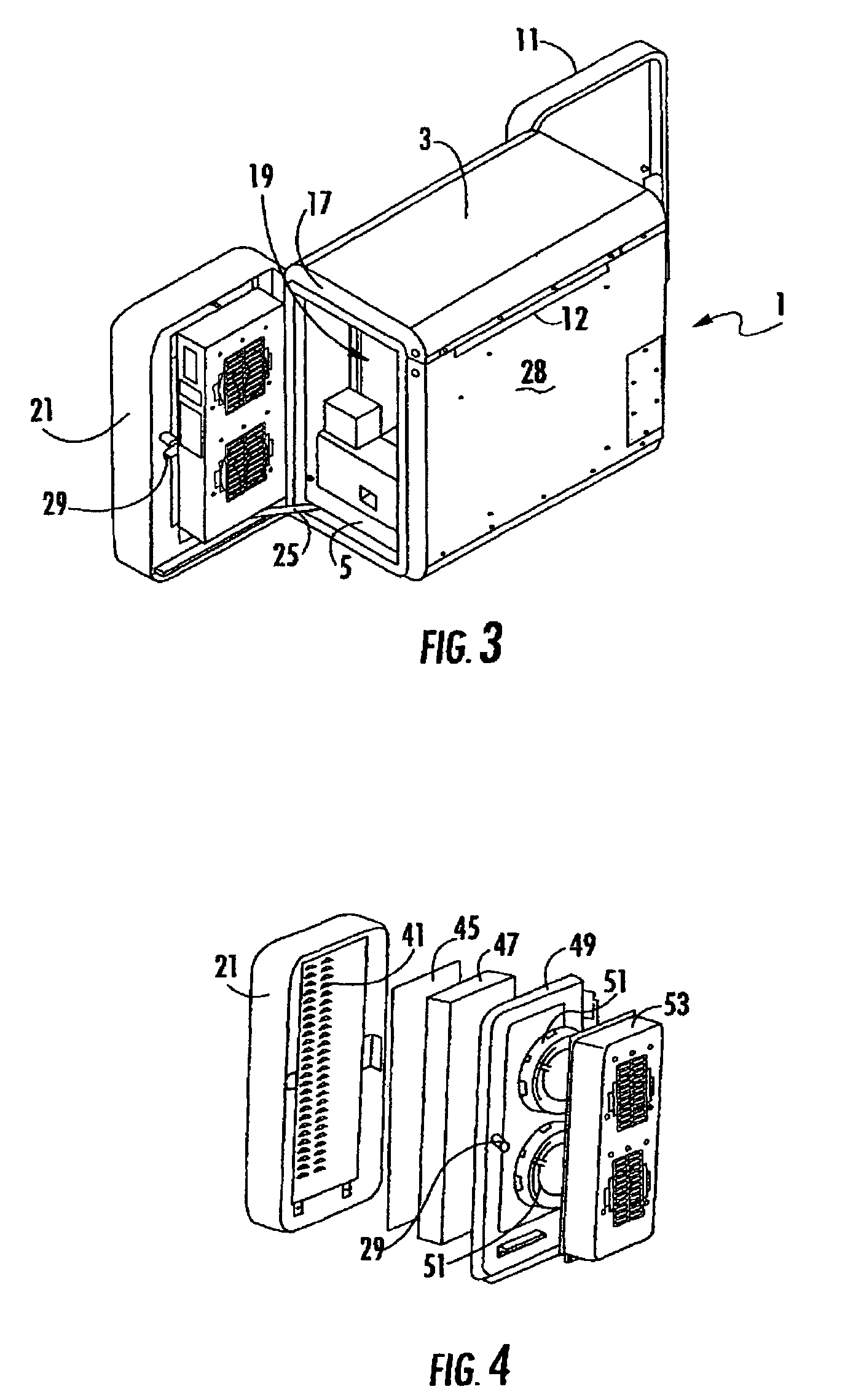
An outdoor equipment cabinet includes a housing with an equipment compartment therein. An intake air vent and an exit air vent are formed in the housing. A fan is mounted within the housing for pulling air into the intake air vent, moving an air stream through the equipment compartment, and pushing air out of the exit air vent. A membrane is disposed adjacent the intake air vent. The membrane allows air to pass therethrough, but resists the passage of water and contaminants therethrough. In some embodiments, a baffling plate is disposed to direct the air stream within the equipment compartment, and / or the fan speed is controlled by a temperature sensor, and / or a clogging of the membrane is monitored and reported, and / or the intake air vent is located in a first door and the exit air vent is located in a second door of the cabinet.

Description

[0001]This application claims the benefit of U.S. Provisional Application No. 60 / 907,249, filed Mar. 27, 2007, the entire contents of which are herein incorporated by reference.BACKGROUND OF THE INVENTION[0002]1. Field of the Invention[0003]The present invention relates to a cabinet. More particularly, the present invention relates to an outdoor cabinet for housing communications equipment, which includes a thermal regulating system to maintain an internal temperature of the cabinet within prescribed limits.[0004]2. Description of the Related Art[0005]There are many types of optical and electronic equipment that must be located in an outdoor environment. For example, telecommunication equipment, networking equipment, and cable television equipment (generally referred to as “communication equipment”) are often housed in an enclosure or cabinet located outdoors. In the communications industry, such equipment is often referred to as “outside plant equipment”. Outside plant equipment ca...

Claims


Application Information

Patent Timeline
Patent Type & Authority Patents(United States)
IPC IPC(8): H05K7/20
CPCH05K7/20563
Inventor HENDRIX, MARKSKREPCINSKI, ALAN
Owner COMMSCOPE INC
Why Eureka
Try Eureka