
Method and assembly for optical reproduction with depth discrimination

a technology of depth discrimination and optical reproduction, applied in the field of methods and assembly for generating optical section images, to achieve the effect of reducing costs

Active Publication Date: 2011-07-12
SCHWERTNER MICHAEL
View PDF16 Cites 14 Cited by
  • Summary
  • Abstract
  • Description
  • Claims
  • Application Information

AI Technical Summary

Benefits of technology

are the average values of C1(x,y) ans C2(x,y), respectively, across an area F, which contains the coordinates (x,y) and covers an integer number of periods of the pattern. The compensation of disadvantageous effects due to inhomogeneous intensities of the illumination patterns (illumination problem or mask imperfections) or inhomogeneous properties of the detector can be compensated by the use of the normalised quantities N1(x,y) and N2(x,y) instead of the recorded quantities I1(x,y) and I2(x,y) in the equations <5, 6, 7, 8>.
[0075]The calculation of optical section images by means of projection and detection of two illumination distributions for each optical section image during the sample scanning mode was demonstrated here using a simplified example of the projection of a continuously variable, sinusoidal illumination pattern. Often, binary patterns are also used because such masks can be manufactured at lower cost. For the reduction of imaging artefacts related to the use of binary or other masks the knowledge of the local phases of the illumination structure is also important and can be accomplished by the calibration step.
[0076]The method described can be realised in a variety of arrangements, especially in wide-field fluorescence microscopes and wide-field microscopes for the investigation and depth profiling von surfaces in EPI-configuration (reflection mode).
[0077]In the following, drawings and arrangements for the implementation of the method according to the invention will be discussed.

Problems solved by technology

Furthermore, one should remove the requirement of pixel-wise alignment of the illuminated structure with the detector, which was necessary so far, but hard to fulfil.

Method used


Image

  • Method and assembly for optical reproduction with depth discrimination
  • Method and assembly for optical reproduction with depth discrimination
  • Method and assembly for optical reproduction with depth discrimination

Examples


Embodiment Construction

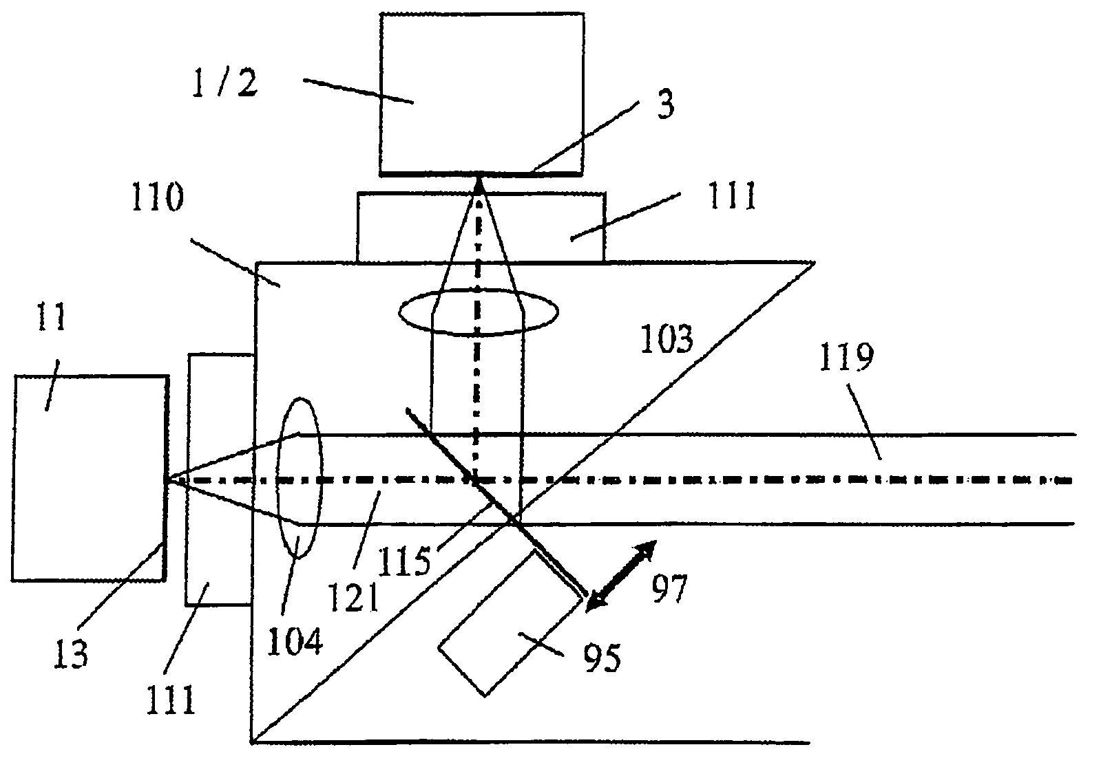
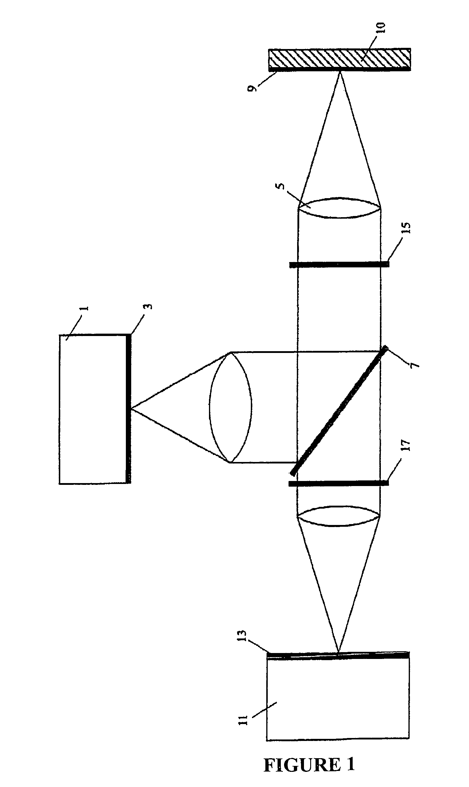
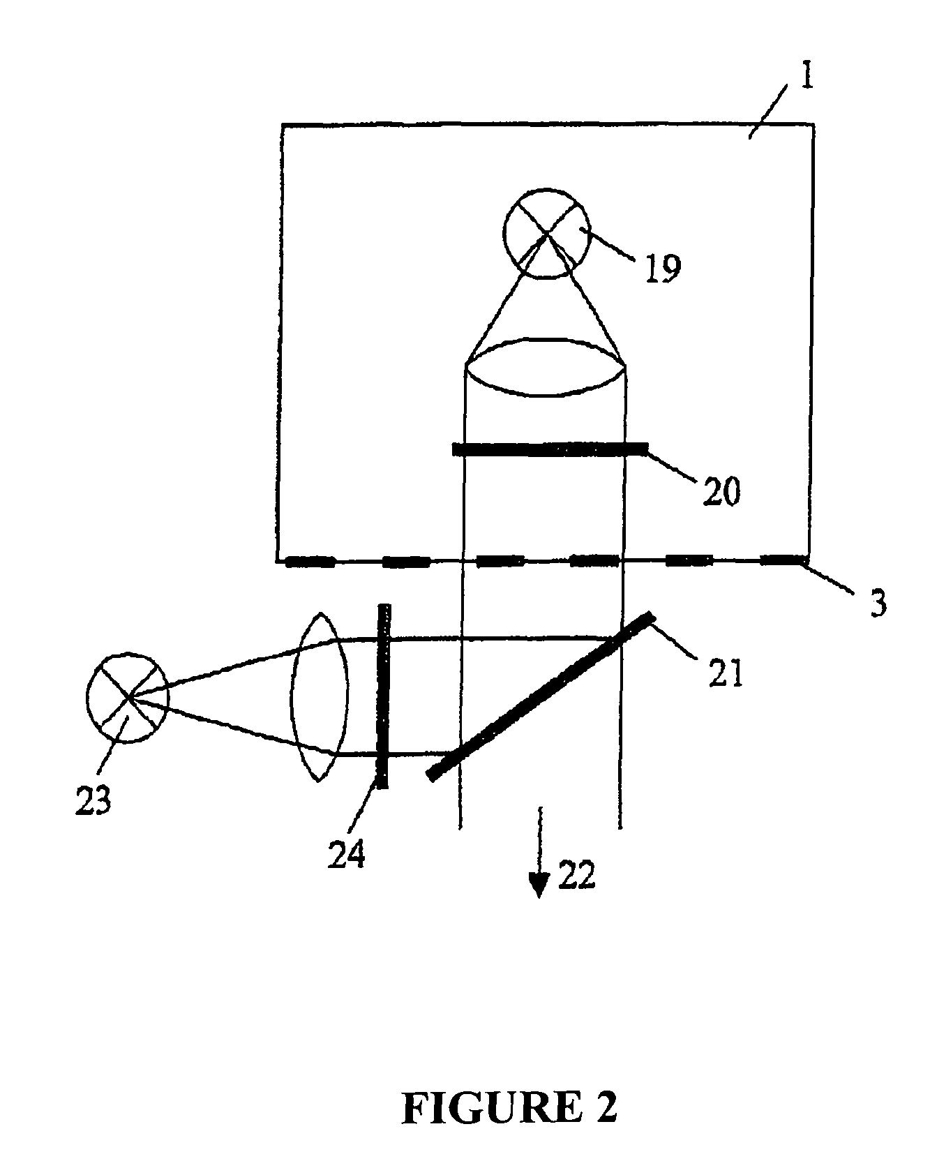
[0096]FIG. 1 shows a simplified arrangement for the implementation of the method. For the sake of simplicity, optional intermediate images and relay optics were not drawn. According to the invention, the illumination unit (1) generates two different illumination patterns. Therefore, an illuminated mask structure, an illuminated DMD chip (digital mirror device, also known as DLP technology by Texas Instruments) or an intermediate image of a light distribution is located in plane (3) and has a modulation in at least one spatial direction.

[0097]Because the term mask or mask structure is used very often within this document, it should be specified more closely: a mask is an optical element, where the physical properties, especially transmission and / or reflection and / or absorption and / or the optical path difference are patterned across the area of the element. If the optical path difference was patterned, one talks about a phase mask which, for example, can be fabricated by etching of st...


PUM


Abstract

A method and an assembly for generating optical section images permit the three-dimensional, layered optical scanning of spatially extended objects. Illumination patterns with periodicity in at least one direction are projected into a plane and the light from the sample which is reflected and / or scattered and / or emitted fluorescence light is being imaged onto a spatially resolving detector. Initially, there is a calibration step, in which the local phase and / or the local period of the illumination patterns are determined for each location on the detector. In the sample detection mode, for the calculation of each optical section image there are two illumination patterns projected into or onto the sample and the resulting intensity distributions are used to form an image on the detector.

Description

CROSS-REFERENCE TO RELATED APPLICATIONS[0001]Not ApplicableSTATEMENT REGARDING FEDERALLY SPONSORED RESEARCH OR DEVELOPMENT[0002]Not ApplicableTHE NAMES OF THE PARTIES TO A JOINT RESEARCH AGREEMENT[0003]Not ApplicableINCORPORATION-BY-REFERENCE OF MATERIAL SUBMITTED ON A COMPACT DISC[0004]Not ApplicableBACKGROUND OF THE INVENTION[0005](1) Field of the Invention[0006]The invention relates to a method and an assembly for generating optical section images.[0007](2) Description of Related Art[0008]In order to create three-dimensional images or mappings of objects, one often uses the technique of optical sectioning. A so-called optical section is an image, which contains information from a certain range of depth. Therefore, an optical system for the generation of optical section images performs selective imaging of those object details which are within the focal plane, while object details outside the focal plane are suppressed in the optical section image.[0009]By means of recording of a ...

Claims


Application Information

Patent Timeline
Patent Type & Authority Patents(United States)
IPC IPC(8): G01D18/00
CPCG01B11/2504G01N21/6458G02B21/367G06T7/0065G06T7/55
Inventor SCHWERTNER, MICHAEL
Owner SCHWERTNER MICHAEL
Learn More