Staggered intake valve opening with bifurcated port to eliminate hydrogen intake backfire

a technology of intake valve and bifurcation port, which is applied in the direction of combustion air/fuel air treatment, electric control, instruments, etc., can solve the problems of not having the bandwidth to control the injection event, reducing the potential for easily ignitable hydrogen, and reducing the potential , to achieve the effect of reducing the potential, easy ignitable hydrogen, and improving fuel economy and/or emissions

Inactive Publication Date: 2011-07-19
FORD GLOBAL TECH LLC
View PDF11 Cites 7 Cited by
  • Summary
  • Abstract
  • Description
  • Claims
  • Application Information

AI Technical Summary

Benefits of technology

[0001]Engines may utilize hydrogen fuel injection to improve fuel economy and / or emissions. In one approach, port fuel injection of hydrogen may be used, where gaseous fuel is delivered to an intake port of each cylinder. With port fuel injection, the injection event may be set to begin after forward air flow in the cylinder (which occurs after intake valve opening and piston downward movement on the intake stroke), and the injection event may be set to end at approximately bottom dead center of the intake stroke. Such a setting reduces the potential for easily ignitable hydrogen to be present in the intake port or manifold for exposure to hot exhaust residual / hot combustion chamber metal surfaces for the subsequent engine cycle.
[0005]In this way, it is possible to reduce backfires since initially fresh air free of hydrogen cools the charge, so that when the hydrogen enters the cylinder, it does not contact overly hot surfaces or other charge.

Problems solved by technology

Such a setting reduces the potential for easily ignitable hydrogen to be present in the intake port or manifold for exposure to hot exhaust residual / hot combustion chamber metal surfaces for the subsequent engine cycle.
Further, such hydrogen can be prone to igniting due to hot gases / metal temperature, potentially causing an undesirable intake backfire.
However, while higher bandwidth injectors may be helpful, they still may not have the bandwidth to control the injection event to only occur during the intake event under all conditions.
For example, the injector bandwidth may be insufficient to provide such control at low speeds and loads as well as at high speeds and loads.

Method used


Image

  • Staggered intake valve opening with bifurcated port to eliminate hydrogen intake backfire
  • Staggered intake valve opening with bifurcated port to eliminate hydrogen intake backfire
  • Staggered intake valve opening with bifurcated port to eliminate hydrogen intake backfire

Examples


Embodiment Construction

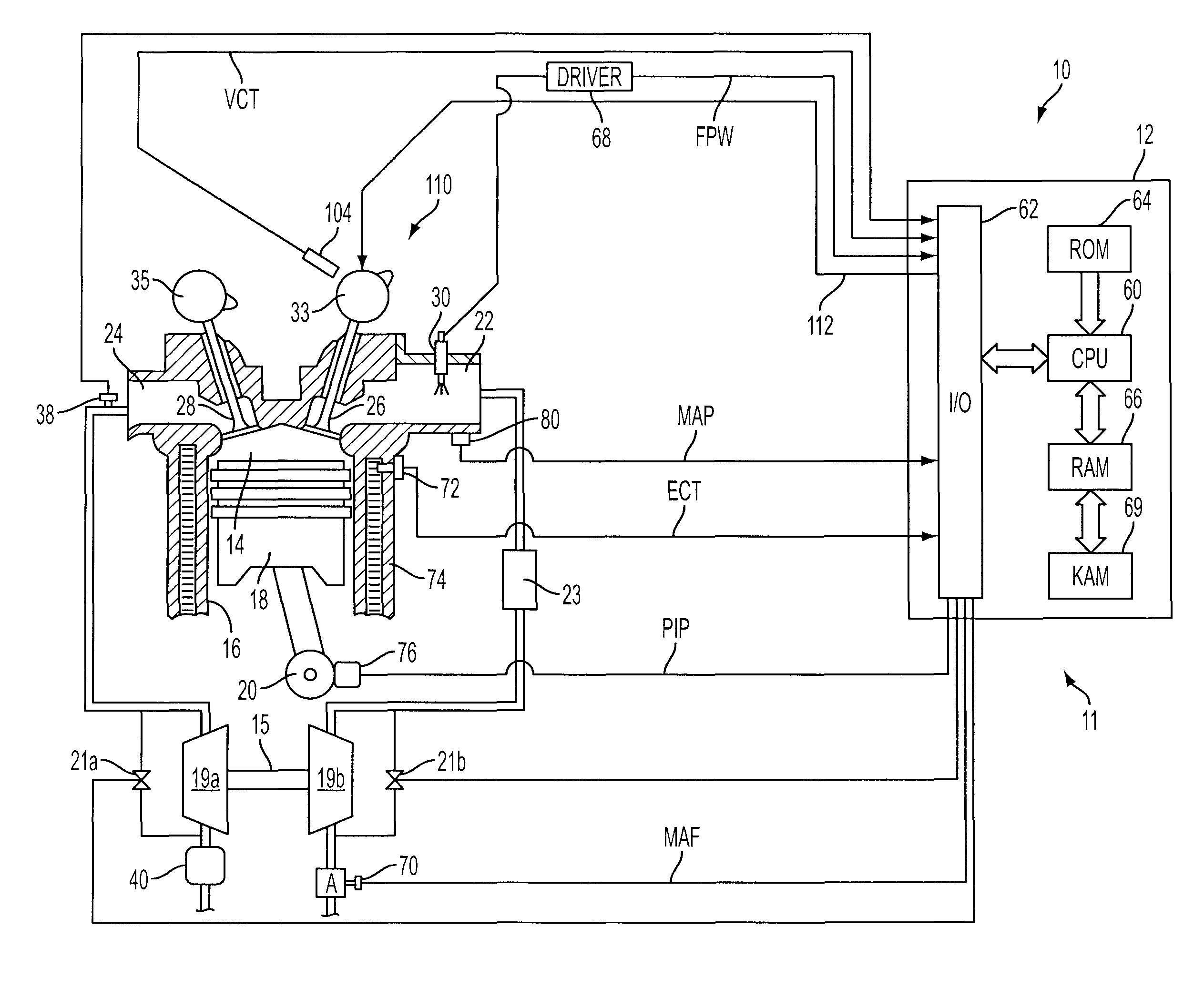
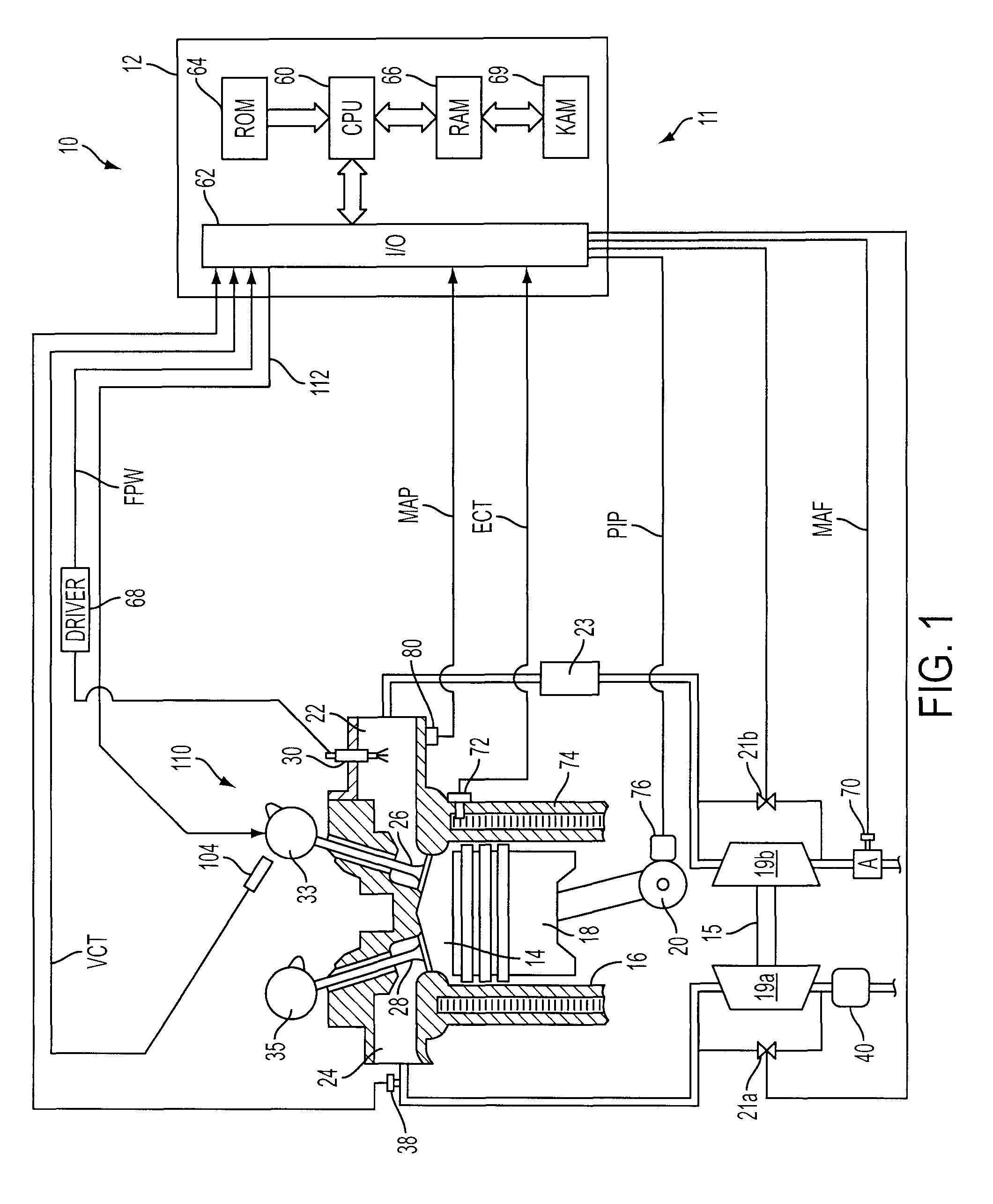
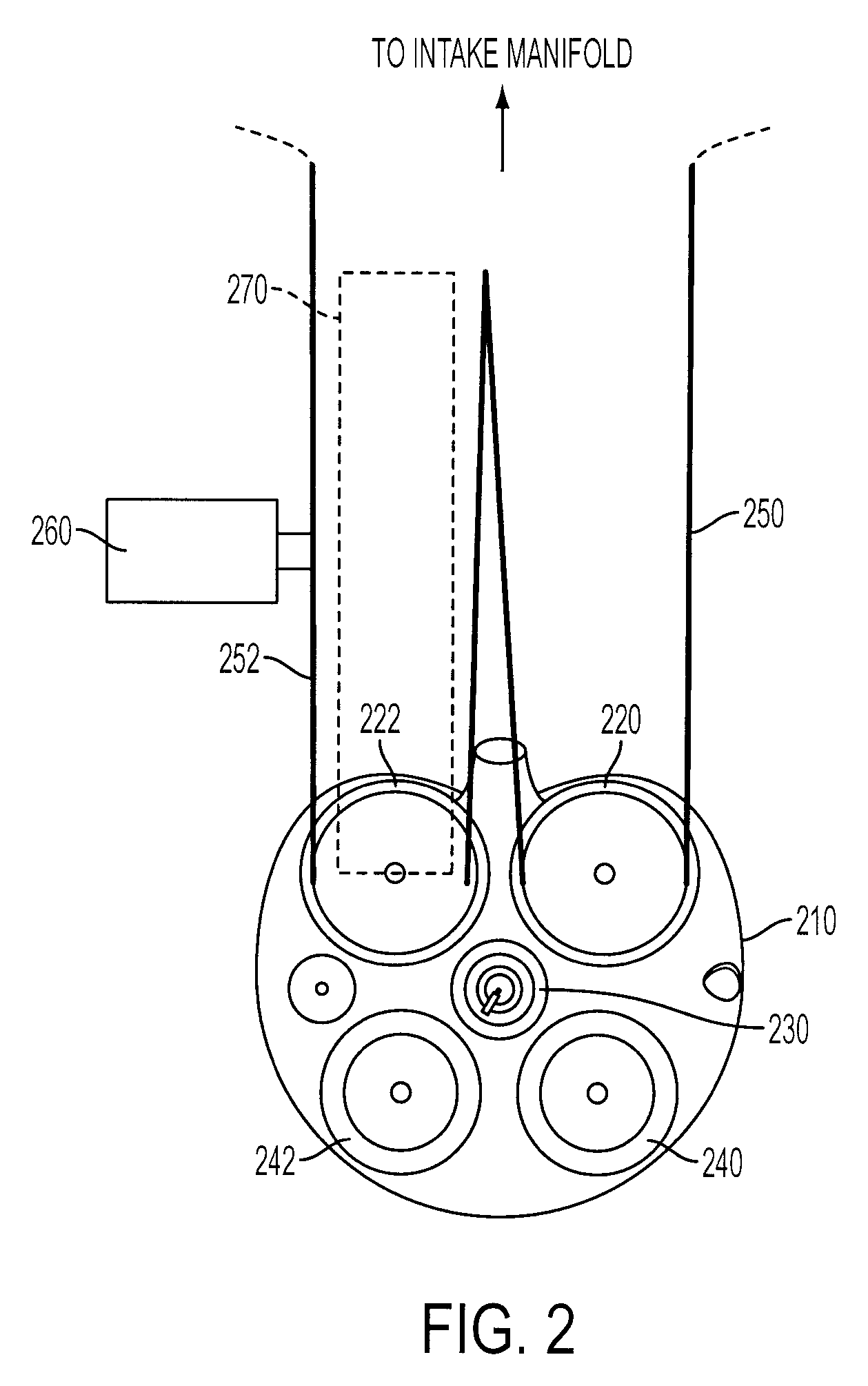
[0012]FIG. 1 shows, generally at 10, an exemplary embodiment of one cylinder of a multi-cylinder engine, intake and exhaust paths connected to that cylinder. It will be appreciated that the configuration of engine 10 is merely one example, and numerous variations are possible. FIG. 2 shows an example intake port configuration that may be used with engine 10, such that engine 10 may be operated with hydrogen fuel to achieve improved resistance against engine backfire due to its intake port design staggered intake valve timing, as described further herein.

[0013]Continuing with FIG. 1, engine 10 is controlled by a control system 11 that may include on or more controllers, such as electronic engine controller 12. Combustion chamber, or cylinder, 14 of engine 10 is shown including combustion chamber walls 16 with piston 18 positioned therein and connected to crankshaft 20. Combustion chamber 14 is shown communicating with intake manifold 22 and exhaust manifold 24 past intake valve(s) 26...


PUM


Abstract

A method is described for operating a gaseous fueled engine, where gaseous fuel and intake air are delivered to a first intake port of a cylinder of the engine and intake air without gaseous fuel is delivered to a second intake port of the cylinder, the first port separated from the second port. Further, the method includes inducting the fuel and intake air from the first port via a first intake valve, and the intake air from the second port via a second intake valve, into the cylinder, where the first intake valve is opened after the second intake valve.

Description

BACKGROUND AND SUMMARY[0001]Engines may utilize hydrogen fuel injection to improve fuel economy and / or emissions. In one approach, port fuel injection of hydrogen may be used, where gaseous fuel is delivered to an intake port of each cylinder. With port fuel injection, the injection event may be set to begin after forward air flow in the cylinder (which occurs after intake valve opening and piston downward movement on the intake stroke), and the injection event may be set to end at approximately bottom dead center of the intake stroke. Such a setting reduces the potential for easily ignitable hydrogen to be present in the intake port or manifold for exposure to hot exhaust residual / hot combustion chamber metal surfaces for the subsequent engine cycle.[0002]However, as engine speed increases, a given injection amount, or pulsewidth, may result in a proportionally greater injector duty cycle as a function of crank angle. If the injection duration is longer than the intake duration (e....

Claims


Application Information

Patent Timeline
Patent Type & Authority Patents(United States)
IPC IPC(8): F02D41/30F02M9/12
CPCF02B17/00F02D13/0238F02D13/0257F02D41/0027F02M35/10216F02M35/10275F02M35/1085F02M67/14F02D19/024F02B29/0406F02B37/00F02B2275/16F02D41/345F02D2041/001Y02T10/123Y02T10/32F02M21/0206F02M21/0278Y02T10/18Y02T10/12Y02T10/30F02D19/02F02M21/02
Inventor BOYER, BRAD ALANJUNG, HOSUK HOWARDSTOCKHAUSEN, WILLIAM FRANCIS
Owner FORD GLOBAL TECH LLC
Why Eureka
Try Eureka