Systems and methods for assessing weather in proximity to an airborne aircraft

a technology for assessing weather and airborne aircraft, which is applied in the direction of climate sustainability, instruments, measurement devices, etc., can solve the problems of not being able to provide the above-described aircraft weather radar system is not particularly sophisticated in providing analyzed information to the crew, and the system may not always present the most reliable and useful information to the crew

Active Publication Date: 2011-07-19
HONEYWELL INT INC
View PDF60 Cites 55 Cited by
  • Summary
  • Abstract
  • Description
  • Claims
  • Application Information

AI Technical Summary

Problems solved by technology

And, a very strong intensity may be associated with very heavy precipitation that may present a hazard to the aircraft.
However, the above-described aircraft weather radar systems are not particularly sophisticated in providing analyzed information to the crew.
Further, such simplistic weather models used by such aircraft weather radar systems may not always present the most reliable and useful information to the crew.
Yet the conventional aircraft weather radar system is not able to differentiate between characteristics of the storm based on geography.
For example, the crew will not be able to immediately discern weather or not the storm cell is growing or decaying by viewing the radar system display.
Further, based upon experience, the crew may suspect that there is lightning, hail or the like in the weather.
Subjectively interpreting the radar images by the crew increases the “cognitive work load” placed on the crew.
Based on their interpretation of the radar images, the crew may elect to alter their flight plan to avoid weather that they think may be potentially hazardous.
The deviation from the flight plan typically adds additional air time and mileage to travel to the destination, thus increasing fuel costs.
However, even though the radar image led the crew of the aircraft to conclude that the weather was potentially hazardous, it may be that the weather was, in fact, not hazardous and was safe to travel through.

Method used


Image

  • Systems and methods for assessing weather in proximity to an airborne aircraft
  • Systems and methods for assessing weather in proximity to an airborne aircraft
  • Systems and methods for assessing weather in proximity to an airborne aircraft

Examples


Embodiment Construction

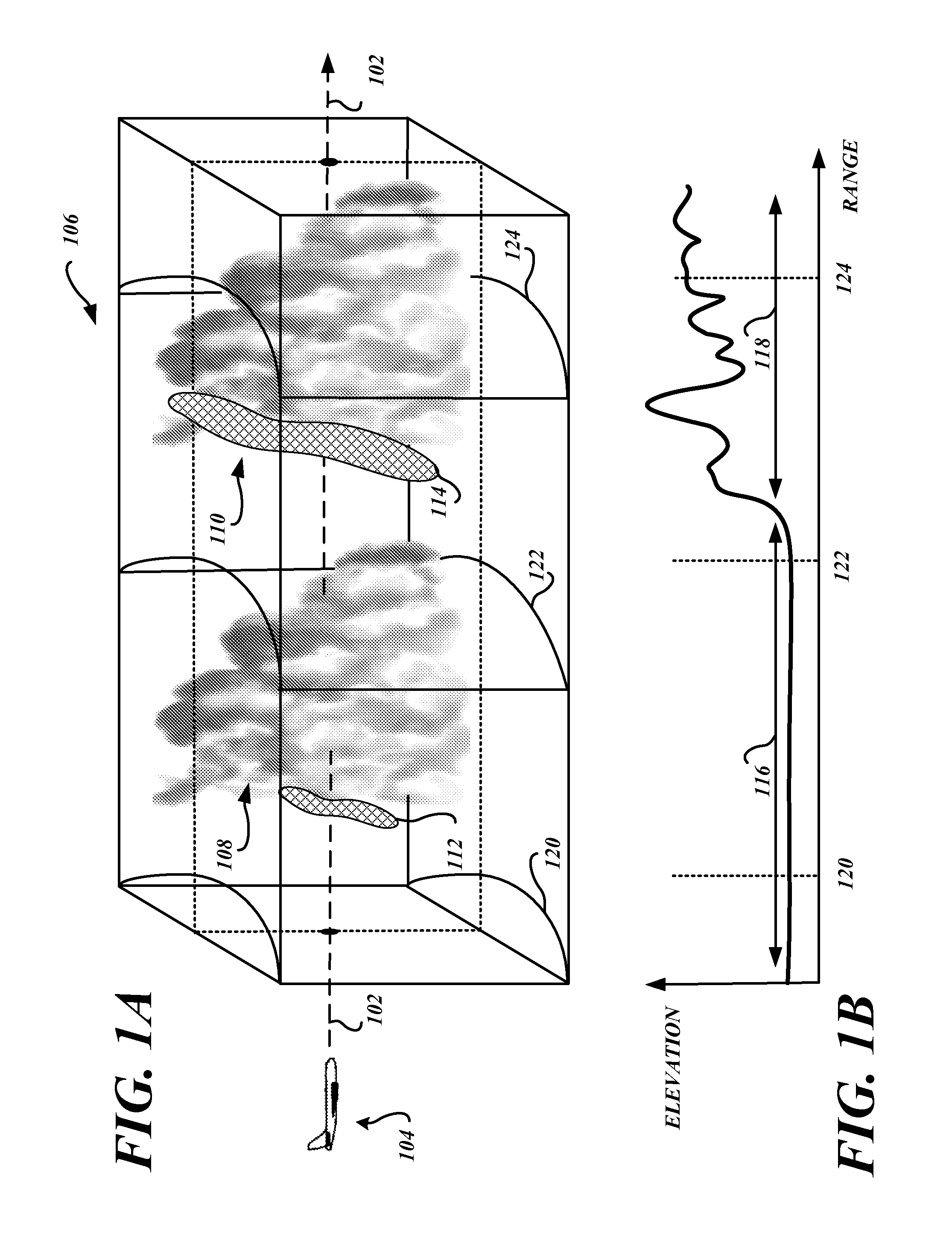
[0021]FIG. 1A is a perspective view of a portion of a planned flight path 102 of an airborne vehicle, such as an aircraft 104 or the like, through a region of space 106 having radar-detectable weather, such as the two storm cells 108, 110. FIG. 1B is a profile view along the planned flight path of the aircraft 104. Here, the aircraft 104 will be traversing through weather that is over very different geographies. The aircraft 104 may commercially transport goods and / or people. The term “weather” generally refers to any type of weather radar detectable weather phenomena, such as, but not limited to, storm cells, turbulence regions, lightning, precipitation, hail, snow, wind shear, icing conditions, and the like that the aircraft 104 may encounter.

[0022]Associated with each storm cell 108, 110, in this illustrative example, is a turbulence region 112, 114, respectively. The illustrated turbulence region 112 resides along the front side of the storm cell 108 and generally lies along the...


PUM


Abstract

Dynamic weather model systems and methods are operable to assess weather in proximity to an airborne aircraft. An exemplary embodiment receives a radar return from the weather, determines reflectivity information from the received radar return, retrieves a weather model from a weather model data base, compares the weather with the retrieved weather model and the determined reflectivity information, predicts a characteristic of the weather based upon the comparison of the weather and the weather model, and determines if the predicted characteristic is potentially hazardous to the airborne aircraft. The weather model is defined by at least one weather modeling algorithm, and is defined by at least one of a parameter and a variable parameter range residing in a weather characteristics database.

Description

BACKGROUND OF THE INVENTION[0001]An aircraft weather radar system emits a pulsed signal, or a series of pulsed signals, in a predefined direction (azimuth) from its antenna. When the pulsed signal is incident on weather that lies along the direction of the emitted pulsed signal, a portion of the pulsed signal is reflected back from precipitation within the weather. The radar antenna detects the returned radar signal. Analysis of the received radar signal permits determination of the distance, or range, of the weather from the radar system.[0002]The intensity of the reflectivity information in the received radar signal may be used to determine characteristics of the weather. Reflectivity information is determined as the result of the processing of raw radar return data. Reflectivity information may include normalized return power estimates, return level statistics such as standard deviation, variance, autocorrelation and higher order moments and Doppler frequency statistics such as m...

Claims


Application Information

Patent Timeline
Patent Type & Authority Patents(United States)
IPC IPC(8): G01S13/95
CPCG01S13/953G01S7/062Y02A90/10
Inventor KAUFFMAN, DONALD C.BUNCH, BRIAN P.
Owner HONEYWELL INT INC
Why Eureka
Try Eureka