
Energy efficient method of monitoring and controlling an HVAC system

a technology of hvac system and energy saving, applied in the direction of instruments, heating types, static/dynamic balance measurement, etc., to achieve the effect of maximizing the efficiency of the building and reducing the design cos

Inactive Publication Date: 2011-07-19
KASSEL EDWARD A
View PDF7 Cites 6 Cited by
  • Summary
  • Abstract
  • Description
  • Claims
  • Application Information

AI Technical Summary

Benefits of technology

The system effectively reduces energy consumption by predicting trends and adjusting operational parameters, allowing for automated energy savings and extended data storage, applicable beyond HVAC systems for various environmental control applications.

Problems solved by technology

Bayesian inference usually relies on degrees of belief, or subjective probabilities, in the induction process and does not necessarily claim to provide an objective method of induction.

Method used


Image

  • Energy efficient method of monitoring and controlling an HVAC system
  • Energy efficient method of monitoring and controlling an HVAC system
  • Energy efficient method of monitoring and controlling an HVAC system

Examples


Embodiment Construction

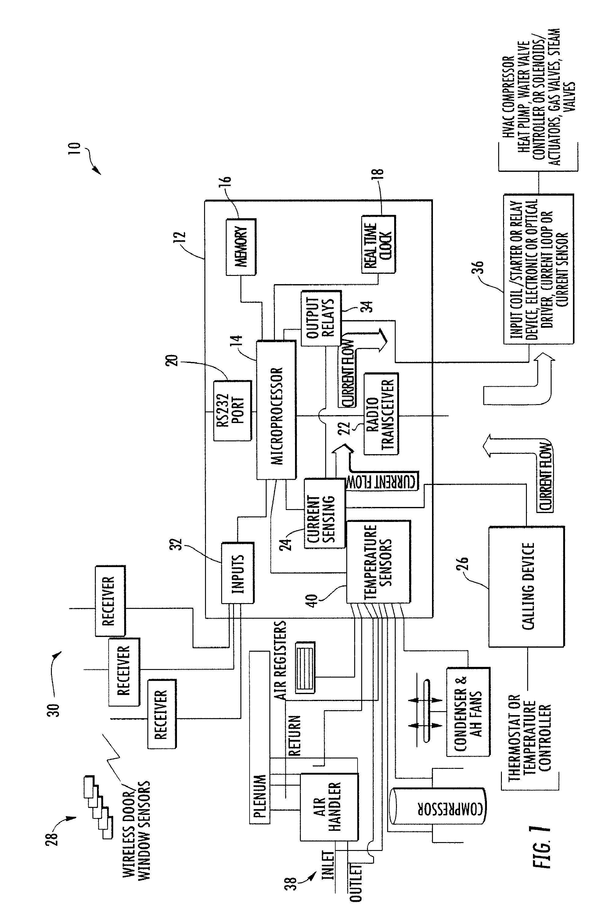
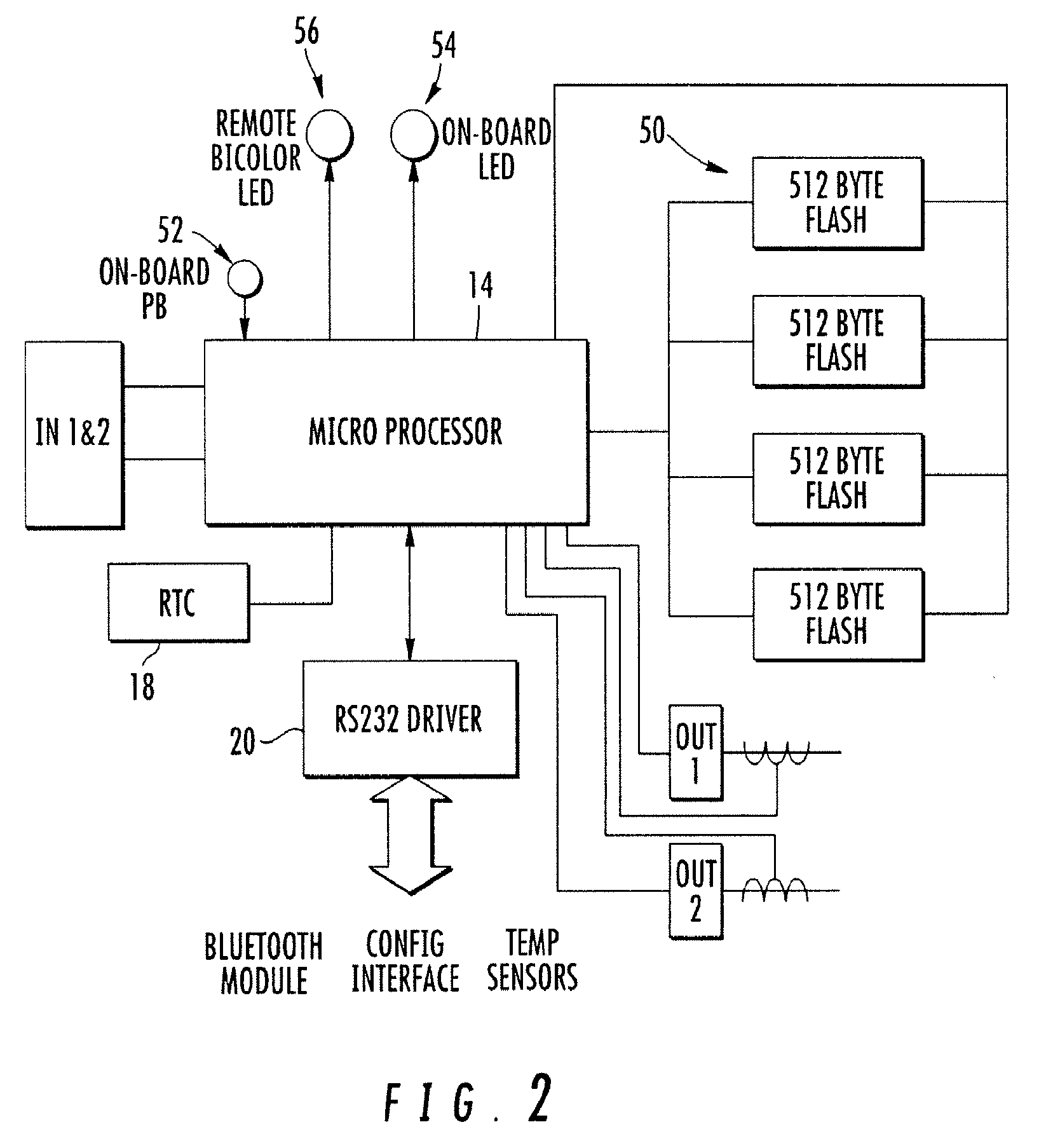
[0031]FIG. 1 is a functional block diagram of one embodiment of a system 10 in accordance with the present invention. A controller 12 is shown to include a microprocessor 14 and memory 16 for carrying out the steps of the program residing in the memory. In one embodiment, the memory includes embedded software to provide software control to the various interfaces to the controller. A real time clock 18 is provided. The RTC 18 is a key factor in keeping all data gathered valid and useful within the record format. One task of the RTC includes providing date and time stamp information as will be appreciated from the description herein. An RS-232 port 20 is included and represents various interfaces. For example, the port may provide the ability to interface with a remote personal computer, personal digital assistant (PDA) or similar device, to provide capability to upload or download data. In addition, the port may accommodate a BLUETOOTH® interface. The BLUETOOTH® interface may provide...


PUM


Abstract

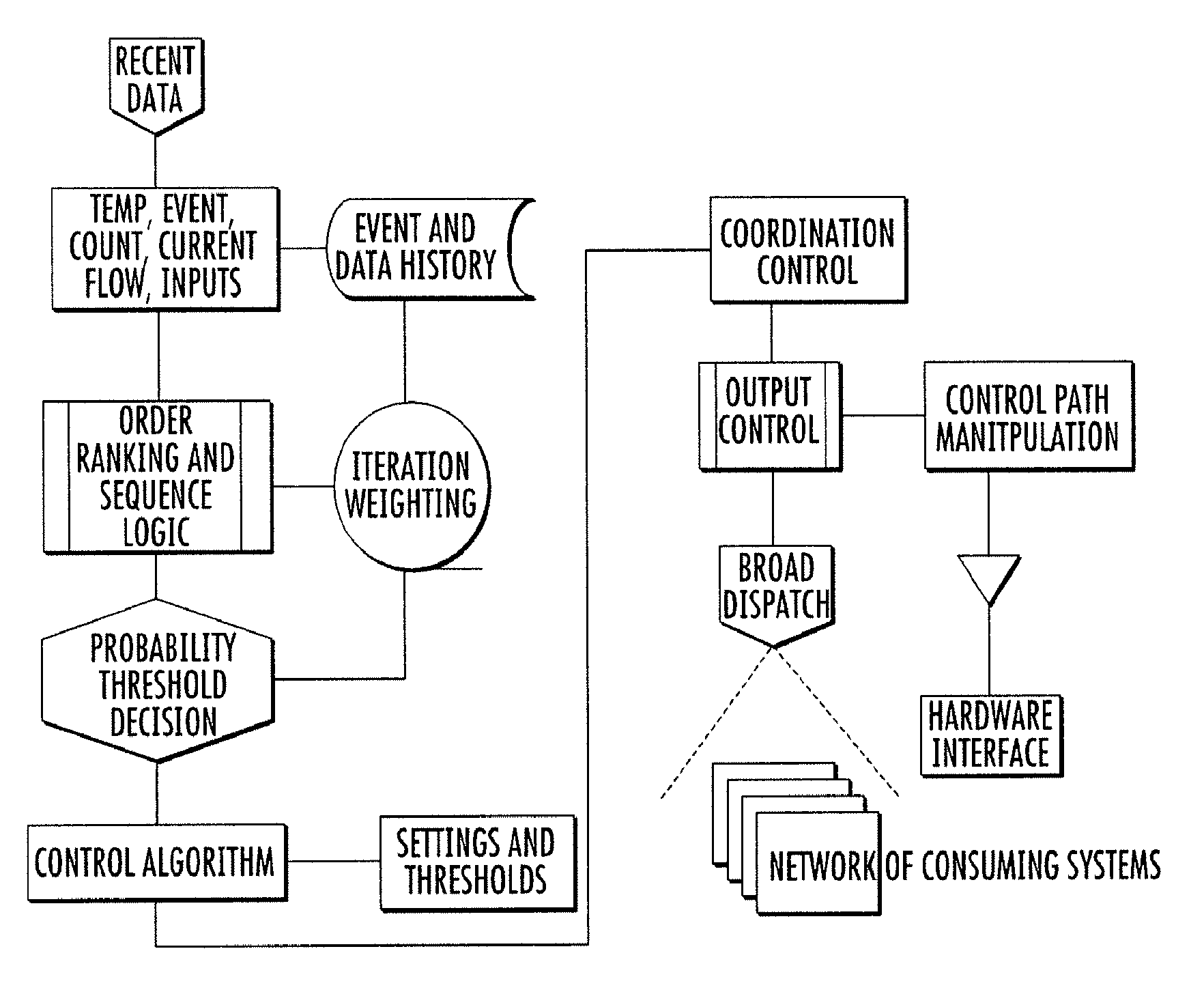
A method of monitoring and controlling an active environmental control system to impose energy efficient use of the system. The method includes the steps of monitoring a calling device for a change in calling data, time and date stamp the change in calling data, detecting a change in status of a plurality of physical sensors located within the system, wherein the state of each sensor represents a condition of the environment in which the system resides, time and date stamp the change in status of the plurality of physical sensors, measuring the temperature of a plurality of temperature locations within the system, time and date stamp the measured temperature of the temperature locations, storing for an extended period the calling data, the status change of the physical sensors and the measured temperature of the plurality of temperature locations, together with the respective time and date stamp, in a memory of the system, filtering the calling data, the physical sensors status change and the measured temperature for a system control trigger to identify system control trigger data, extracting a probability decision, to predict a direction of trend, by comparing recent system control trigger data with prior recorded system control trigger data, weighting the system control trigger data, based on the probability decision that the data is causing the output event trigger, in order to effect a desired change in output, and controlling the system based on the weighted system control trigger data.

Description

CROSS-REFERENCE TO RELATED APPLICATIONS[0001]This application claims the benefit of U.S. Provisional Application No. 60 / 826,417, filed Sep. 21, 2006.FIELD OF INVENTION[0002]An intelligent method for monitoring and controlling active heating / ventilating and air conditioning equipment for the purpose of energy savings and, in particular, using current and prior system performance to anticipate necessary system control in order to obtain a desired energy efficiency.BACKGROUND OF THE INVENTION[0003]The prior art includes heating / ventilation and air conditioning (HVAC) systems which typically include a furnace or boiler to heat air or water. The system includes a means of conveying the heat to other locations. The conveying means is typically ductwork for a furnace and piping for a boiler. The air conditioning half of the system typically includes a compressor, condenser, evaporator and a metering device. A thermostat is coupled to a controller for controller the above components of the ...

Claims


Application Information

Patent Timeline
Patent Type & Authority Patents(United States)
IPC IPC(8): G05D23/00
CPCF24F11/0086G05D23/193F24F11/0012F24F2011/0061G05D23/1931F24F11/30F24F2110/10F24F11/63F24F11/46
Inventor KASSEL, EDWARD A.
Owner KASSEL EDWARD A
Learn More