Method and apparatus for digital synthesis of long multi-cycle microwave pulses

a multi-cycle, microwave technology, applied in pulse train generators, pulse techniques, line-transmission details, etc., can solve the problems of short microwave pulse radiation, limited power, and inability to produce clean microwave pulses, and achieve the effect of increasing the mismatch in the extraction of low-z energy, introducing more losses in low-z lines, and increasing the impedan

Inactive Publication Date: 2011-07-26
BAE SYST INFORMATION & ELECTRONICS SYST INTERGRATION INC
View PDF7 Cites 6 Cited by
  • Summary
  • Abstract
  • Description
  • Claims
  • Application Information

AI Technical Summary

Benefits of technology

[0021]According to the present invention, conductive segments (transmission line conductors) are positioned within a transmission line structure in order to generate multi-cycle microwave pulses. The conductive segments are switchable coupled to one or the other conductor of the transmission lines, inside the transmission line structure. Microwave pulses may be induced in the transmission line by closing the switches in a controlled manner to discharge successive segments, or successive groups of segments, into the transmission lines. The induced pulses travel uninterrupted along the transmission lines in a desired direction to the load. Efficiency of systems and energy delivered to the load according to the present invention is increased and / or maximized by adjusting the ratio of characteristic impedances associated with the positions of transmission line conductive segments according to an optimum ratio.
[0027]By increasing the ratio D2 / D1 and keeping a low-Z impedance, i.e. low D1, conductive losses in pulses propagated to the load decrease due to lower currents. On the other hand, typically, when the ratio D2 / D1 increases, the mismatch in extracting the energy from low-Z lines is also increased and more reflections introduce more losses in low-Z lines. However, all lines are charged and in the first few sections the number of “active” reflections gradually decreases. For each of the following sections, the number of meaningful reflections in the low-Z lines is lower compared to that expected from the large D2 / D1 ratio. This gives a very efficient (low loss) process of extracting energy from high energy storage, low-Z lines, and in combination leads to a low transfer losses to the load even for a high number of sections. The resulting improvement in total load energy (longer overall pulse length with higher power) comes at the expense of increased volume of the transmission-line system.

Problems solved by technology

The coupling of the resulting pulse train to a load such as an antenna results in the radiation of a short microwave pulse.
Unfortunately, the arrangements described by Driver et al. and Mourou do not produce clean microwave pulses and are limited in power since TE waveguides have impedances close to that of free space, typically 50 ohms or more, and therefore cause the LASS switches to operate outside the electric field and current density limits consistent with good high power design principles, specifically, unidirectional power flow in a continuously matched system.
Despite the above advantages, the implementation of a transmission line as a series of segments coupled together by switches causes problems when trying to provide a number of pulses in series.
Thus, sequential switching systems are not desirable for certain applications because of attenuation problems and are limited by a low number of pulses.
Therefore, energy delivered to resistive load is relatively low.
With the increase in physical and electrical length, however, conductive losses associated with generating pulses traveling to the load also increase and the efficiency of the generator decreases.
Therefore, even in configurations with switching elements positioned in parallel to transmission lines, conductive losses can quickly predominate and practically limit the number of sections implemented.
As a result, there is limited power and energy delivered to the load.
In all cases, to achieve the high power / energy on the load, the number of section is a principal limitation.

Method used


Image

  • Method and apparatus for digital synthesis of long multi-cycle microwave pulses
  • Method and apparatus for digital synthesis of long multi-cycle microwave pulses
  • Method and apparatus for digital synthesis of long multi-cycle microwave pulses

Examples


Embodiment Construction

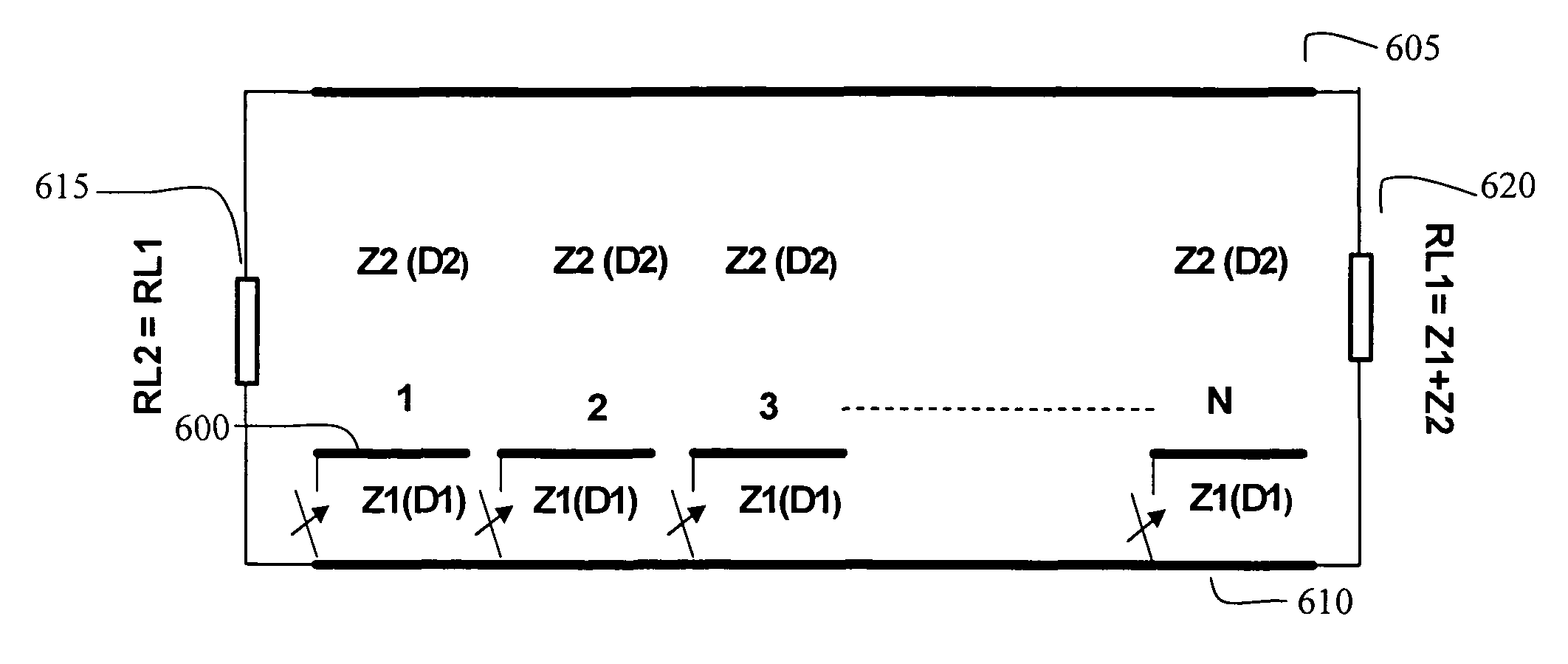
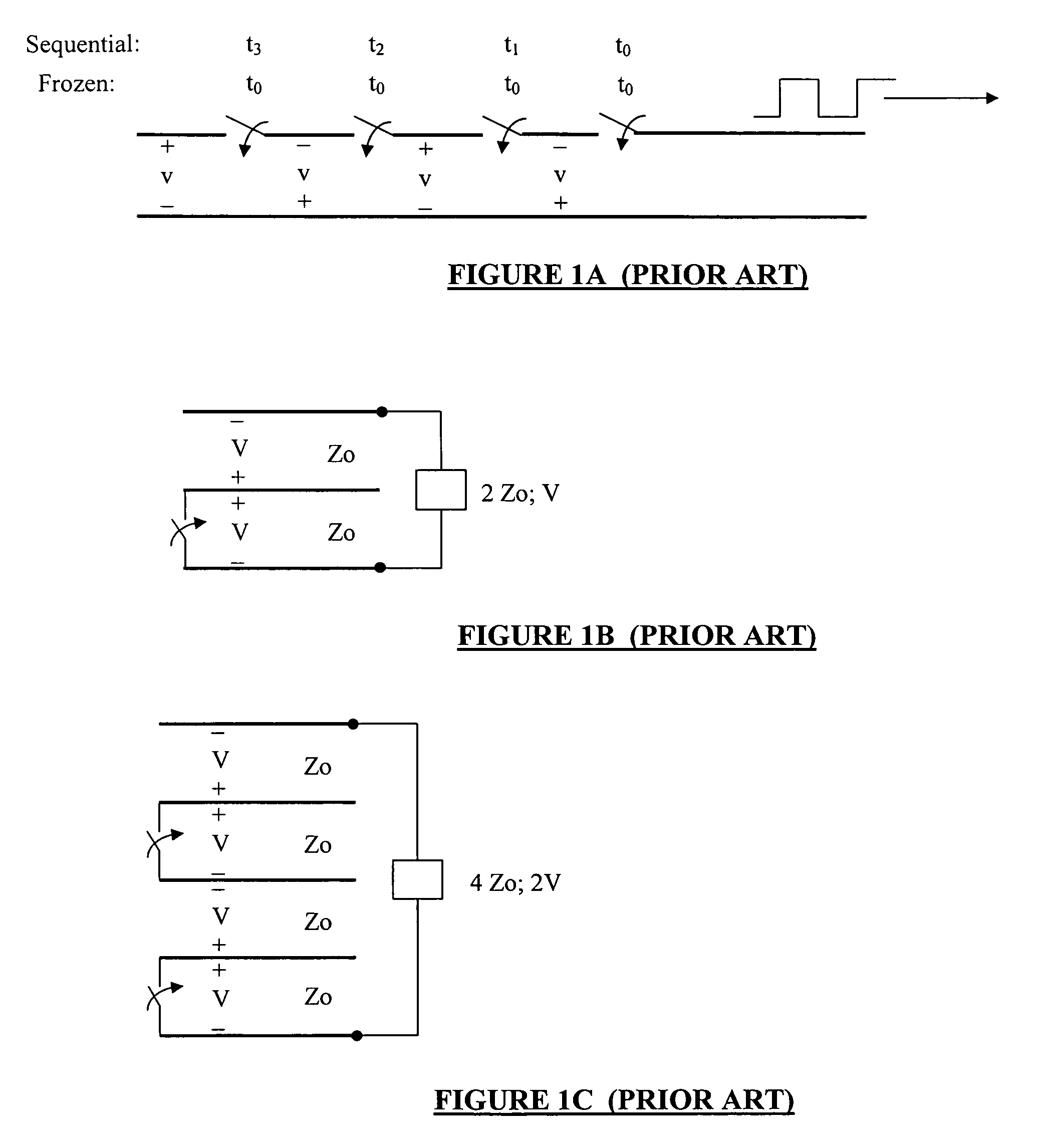
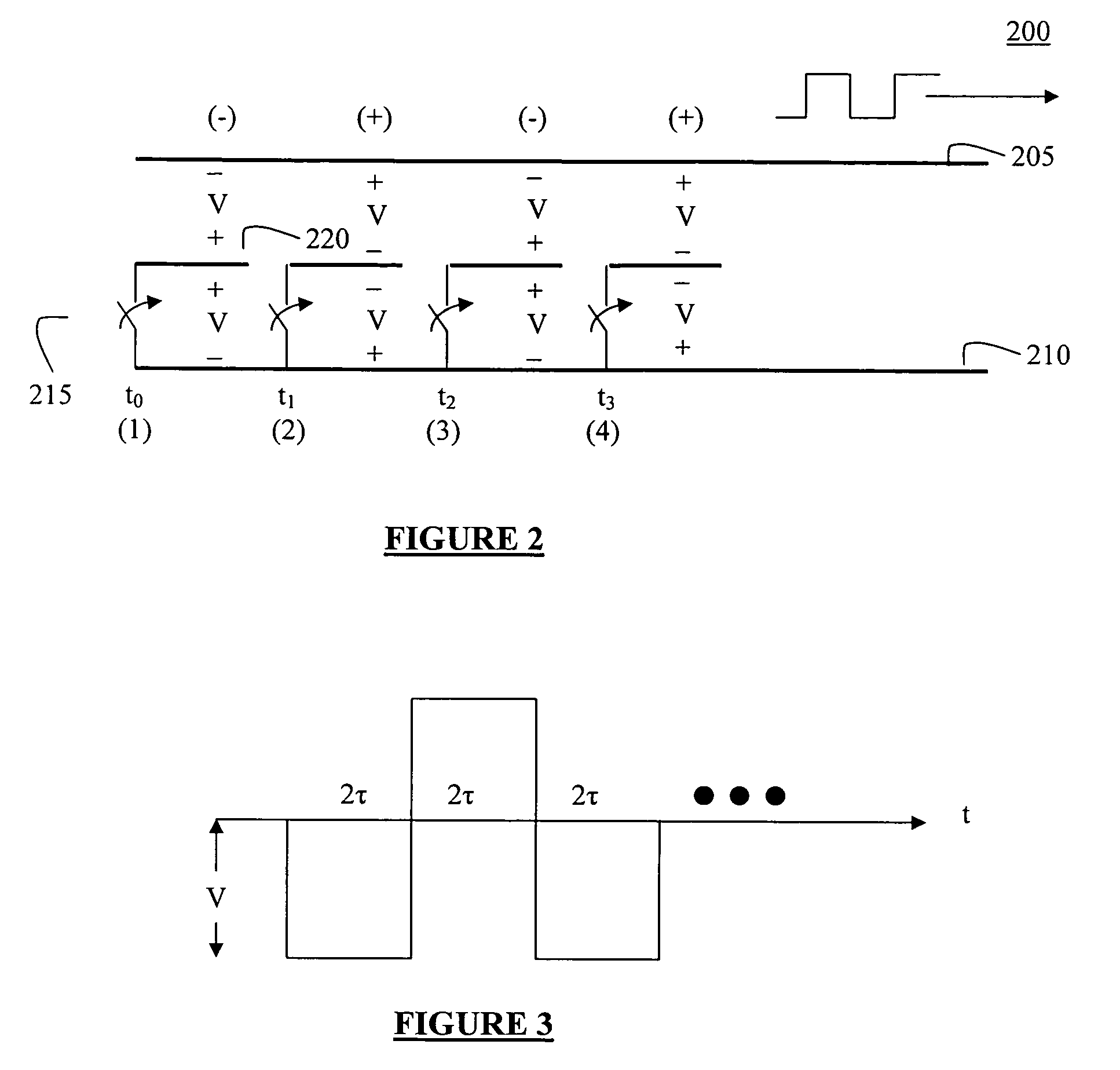
[0043]According to the present invention, conductor segments (transmission line conductors) are positioned within a transmission line structure in order to generate microwave pulses. The conductor segments are switchably coupled to one or the other conductive segment of the transmission lines, while the switches are connected between adjacent segments in the transmission line structure. Microwave pulses may be induced in the transmission line by closing the switches in a controlled manner to discharge successive segments, or successive groups of segments, into the transmission lines. The induced pulses travel uninterrupted along the transmission lines in a desired direction to the load. Efficiency of systems according to the present invention is increased and / or maximized by adjusting the impedance ratio associated with the transmission line conductor segments relative to the transmission lines according to an optimum ratio. In all cases, the lowest characteristic impedance Z1 is re...


PUM


Abstract

Conductive segments (transmission line conductors) are positioned within a transmission line structure in order to generate multi-cycle microwave pulses. The conductor segments are switchably coupled to one or the other conductor of the transmission lines, inside the transmission line structure. Microwave pulses may be induced in the transmission line by closing the switches in a controlled manner to discharge successive segments, or successive groups of segments, into the transmission lines. The induced pulses travel uninterrupted along the transmission lines in a desired direction to the load. Efficiency of systems and energy delivered to the load in multi-section transmission lines is increased and / or maximized by adjusting the ratio of characteristic impedances associated with the transmission line conductor segments according to an optimum ratio.

Description

CROSS REFERENCE TO RELATED APPLICATIONS[0001]This application contains subject matter that is related to the following co-pending patent applications: U.S. patent application Ser. No. 11 / 147,452, entitled Method And Apparatus For Digital Synthesis Of Microwaves Through Balanced Transmission Structures; and Re: U.S. patent application Ser. No. 11 / 147,453, entitled “Method And Apparatus For Digital Synthesis Of Microwaves.”FIELD OF THE INVENTION[0002]The present invention relates to a method and apparatus for generating microwaves and more particularly to a microwave source and a method for generating microwaves by digital synthesis.BACKGROUND OF THE INVENTION[0003]Digital synthesis of microwaves uses transmission lines and switches to generate a series of alternating polarity pulses. The coupling of the resulting pulse train to a load such as an antenna results in the radiation of a short microwave pulse. This approach has been investigated for over 30 years.[0004]The general concept...

Claims


Application Information

Patent Timeline
Patent Type & Authority Patents(United States)
IPC IPC(8): H04B3/04
CPCH03K3/86H03K3/53
Inventor LONDON, SIMON Y.ZUCKER, OVED
Owner BAE SYST INFORMATION & ELECTRONICS SYST INTERGRATION INC
Why Eureka
Try Eureka