Automated traffic violation monitoring and reporting system with combined video and still-image data

a traffic violation and video and still image technology, applied in the field of automated traffic violation monitoring and reporting system, can solve the problems of not being able to facilitate efficient automation and validation of photographs, not showing the acceleration and speed of vehicles, and still images typically not conveying enough information, so as to achieve the effect of reducing the requirements of data transfer and storag

Inactive Publication Date: 2011-07-26
REDFLEX TRAFFIC SYST
View PDF49 Cites 78 Cited by
  • Summary
  • Abstract
  • Description
  • Claims
  • Application Information

AI Technical Summary

Benefits of technology

[0008]It is an object of embodiments of the present invention to combine high-resolution still digital images and low-resolution video into a single set of information to be used to record the instances of traffic violations in a manner that minimizes data transfer and storage requirements.
[0009]It is a further object of embodiments of the present invention to incorporate a “before” and “after” video sequence that enables reviewers to identify mitigating or aggravating circumstances immediately following or preceding a traffic offense detection.
[0010]It is yet a further object of embodiments of the present invention to provide a means of visually verifying the speed of the detected vehicle without using multiple high-resolution still images.
[0011]It is also an object of embodiments of the present invention to provide a means for easy retrieval of specific incidents or driver / car information from stored or archived data.
[0013]The networked digital camera system houses a conventional still-image digital camera system and a video camera system. The video camera system is configured to record footage both before and after the offense is detected. This provides the law enforcement agency with a more complete record of the events leading up to and following on from the offense itself. This may assist agency staff to better perceive the context of the offense or even detect further offenses by the same vehicle. For instance, a still-imaging system will detect a car both before and after the line at a red light, but with video the offense processing staff may also note that the car entered the intersection to yield to emergency vehicles, or that the car also lost control and became involved in an accident.
[0015]The combination of still and video footage solves the problems associated with the demand for video and the need for high resolution and low storage and transmission costs. Because the still-images continue to provide the high resolution necessary to extract important details from the evidence set, the video record can be captured using low resolution technologies that do not unduly tax the storage and data transmission systems.

Problems solved by technology

However, many current traffic enforcement systems using photographic techniques have disadvantages that generally do not facilitate efficient automation and validation of the photographs required for effective use as legal evidence.
For example, still images typically do not convey enough information to assess the circumstances surrounding a violation.
Still images do not show the acceleration and speed of a vehicle and cannot determine if the vehicle has progressed unlawfully, i.e., without first stopping.
Errors in the vehicle's detected speed will not be apparent on the photograph, as still images do not convey any impression of speed.
Although multiple still photographs may be taken to show speed across two or more points, this solution results in increased image capture and storage requirements and causes the camera to be occupied for the duration of the image sequence.
However, increasing image resolution also increases data storage requirements.
However, the advent of video has certain significant disadvantages.
Most notably, when an enforcement agency wishes to use video in their evidence set, the problems related to transmission bandwidth and data storage is significantly compounded.
Although video footage has been used for identification and prosecution of vehicles in violation of traffic laws, the generally low resolution of present video systems makes it difficult to determine the fine details required for prosecution, such as the vehicle license plate or the features of the driver's face.
The low resolution problem also requires the video camera to be close to the detected vehicle or to physically move and track the vehicle, both of which are major disadvantages when used in automated traffic monitoring systems.
Although high-resolution video cameras can be employed for identification and prosecution of vehicles in violation of traffic laws, if the information from a high-resolution video camera is stored digitally, the amount of file storage required makes it difficult or impractical to store and communicate the amount of information generated.
This is especially true for systems that do not provide efficient video clips, but rather shoot and transmit long loops of constant video data.
The standard start / stop capturing mechanism available in almost all video capture systems is inadequate to satisfy the requirement for providing footage both before and after the offense is detected.
It is also generally difficult to anticipate an offense and preemptively commence video capture.
Furthermore, where the footage from a video system is recorded on magnetic tape the retrieval of information is time consuming and finding a specific violation or incident cannot be done instantaneously.

Method used


Image

  • Automated traffic violation monitoring and reporting system with combined video and still-image data
  • Automated traffic violation monitoring and reporting system with combined video and still-image data
  • Automated traffic violation monitoring and reporting system with combined video and still-image data

Examples


Embodiment Construction

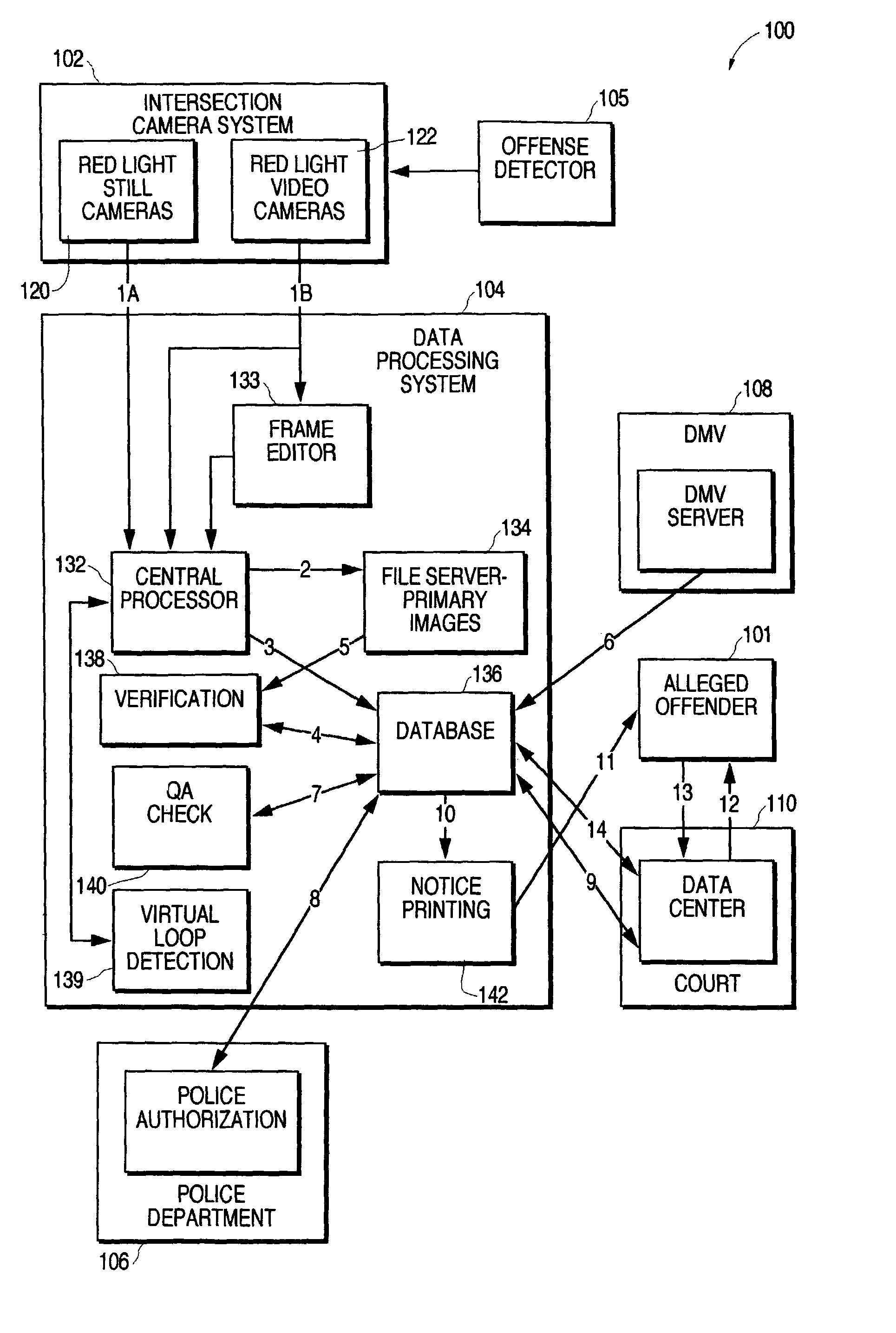
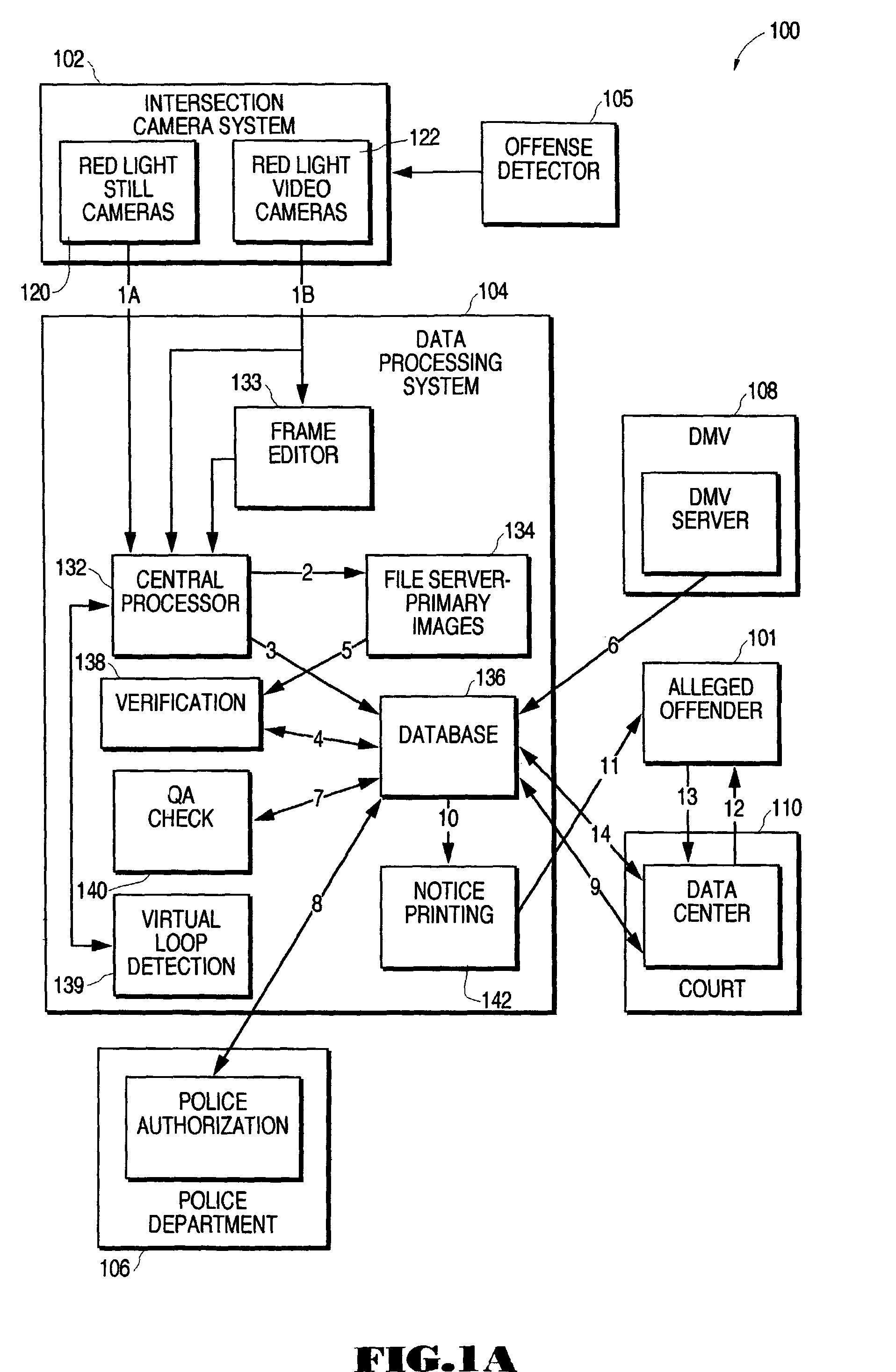
[0044]An automated system for monitoring and reporting incidences of traffic violations utilizing both still and video camera systems is described. In the following description, for purposes of explanation, numerous specific details are set forth in order to provide an understanding of the present invention. It will be evident, however, to those of ordinary skill in the art that the present invention may be practiced without the specific details. In other instances, well-known structures and devices are shown in block diagram form to facilitate explanation. The description of preferred embodiments is not intended to limit the scope of the claims appended hereto.

[0045]FIG. 1A is a block diagram that illustrates the overall traffic violation processing system, according to one embodiment of the present invention. The main components of the traffic violation processing system 100 comprise the intersection camera system 102, an offense detector system 105, the data processing system 104...


PUM


Abstract

A system for monitoring and reporting incidences of traffic violations at a traffic location is disclosed. The system comprises one or more digital still cameras and one or more digital video cameras system deployed at a traffic location. The camera system is coupled to a data processing system, which comprises an image processor for compiling vehicle and scene images produced by the digital camera system, a verification process for verifying the validity of the vehicle images, an image processing system for identifying driver information from the vehicle images, and a notification process for transmitting potential violation information to one or more law enforcement agencies. The video camera system is configured to record footage both before and after the offense is detected. The video camera system includes a non-stop video capture buffer that records the preceding few seconds of violation. The buffer holds a number of seconds of video data in memory. When an offense is detected, a timer is started. At the end of the timer period a video clip of the current buffer contents is recorded. The resulting video clip is incorporated with the conventional evidence set comprising the digital still images of the offense with the identifying data of the car and driver.

Description

FIELD OF THE INVENTION[0001]The present invention relates generally to traffic monitoring systems, and more specifically to a system for detecting and monitoring the occurrence of traffic offenses and providing video and still photographic evidence of offenses to traffic enforcement agencies.BACKGROUND OF THE INVENTION[0002]Camera-based traffic monitoring systems have become increasingly deployed by law enforcement agencies and municipalities to enforce traffic laws and modify unsafe driving behavior, such as speeding running red lights or stop signs, and making illegal turns. The most effective programs combine consistent use of traffic cameras supported by automated processing solutions that deliver rapid ticketing of traffic violators, with other program elements including community education and specific targeted road safety initiatives like drunk-driving enforcement programs and license demerit penalties. However, many current traffic enforcement systems using photographic tech...

Claims


Application Information

Patent Timeline
Patent Type & Authority Patents(United States)
IPC IPC(8): H04N7/18G08G1/017G08G1/042G08G1/054
CPCG08G1/0175G08G1/042G08G1/054
Inventor HIGGINS, BRUCE E.
Owner REDFLEX TRAFFIC SYST
Why Eureka
Try Eureka