
All-LED visible light and IR light headlamp

a technology of visible light and ir light, which is applied in the field of electric illumination, can solve the problems of poor performance characteristics of sealed beam headlamps that have been used in tactical military vehicles for many years, and the operation is more difficult, and many operators consider this ineffectiv

Inactive Publication Date: 2011-08-02
IBIS TEK
View PDF3 Cites 21 Cited by
  • Summary
  • Abstract
  • Description
  • Claims
  • Application Information

AI Technical Summary

Benefits of technology

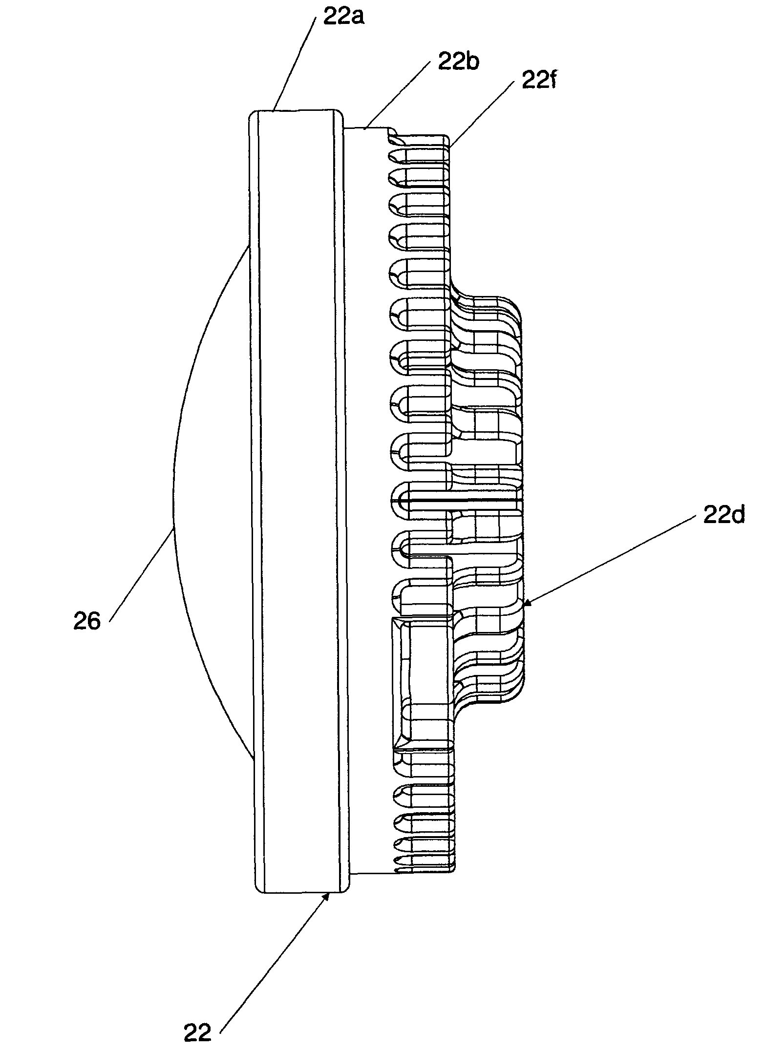
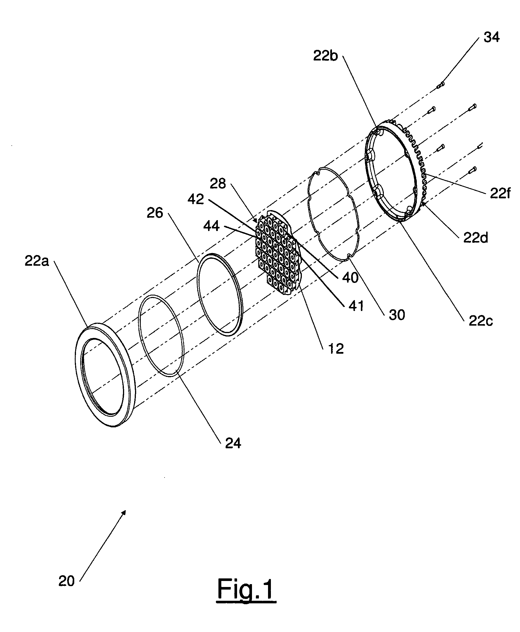
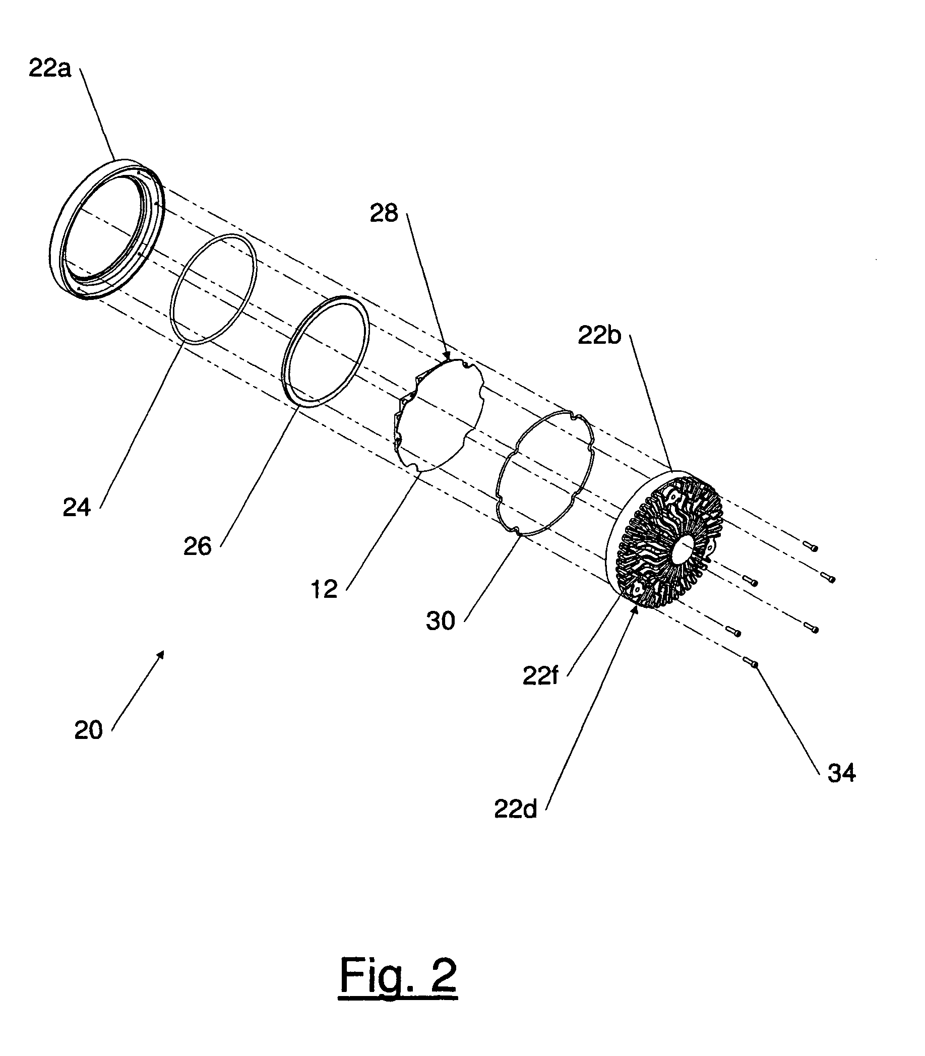
"The invention is an LED headlamp system that uses only visible or infrared light for high or low beam operation. It is designed to dissipate heat from the LEDs through conduction and radiation, making it suitable for use in ground, air, or sea-going vehicles. The technical effect of this invention is to provide a more efficient and effective headlamp system that is more reliable and durable than traditional headlamps that use other light sources."

Problems solved by technology

The sealed beam headlamps that have been used in tactical military vehicles for many years exhibit poor performance characteristics when compared to current automotive lighting systems.
Military “blackout” operations present greater challenges: the vehicle must be operated at night at a moderately high speed without being detected by enemy forces.
Many operators consider this ineffective especially when driving at higher speeds.
Night vision goggles (NVGs) and infrared lighting significantly improve low-light and blackout operations, but NVGs used without providing any sort of illumination are generally considered inadequate for such operations.
IR illumination produced in this fashion is inefficient, since the lamp still produces visible light, and only a small portion of the radiation produced by the lamp is passed as IR.
Additionally, blocking all visible light is difficult, and the filter / lens must be mechanically moved into place, resulting in an unacceptable conversion time to switch between visible and infrared illumination mode.

Method used


Image

  • All-LED visible light and IR light headlamp
  • All-LED visible light and IR light headlamp
  • All-LED visible light and IR light headlamp

Examples


third embodiment

Referring now to FIG. 10, in still another, third embodiment, an LED light source is provided by a plurality of so-called dies 40d thermally bonded to the LED-substrate 12. The light from the plurality of dies 40d is formed into a beam using a single lens 40c 41c 42c 44c 46d, visible as the outermost component of the LED-lens units 40414244 at an appropriate standoff from the dies 40d. Thus, each LED-lens unit 40414244 comprises a plurality of dies 40d and a single lens 40c 41c 42c 44c 46d, the lens selected to produce a desired beam pattern.

Referring now especially to FIG. 7, in an illustrative layout of LEDs 40414244 on an LED mounting substrate 12, the LED array 28 includes a first high-beam visible-light LED assembly 40a comprising of two visible-light LED-lens units 40 disposed closest to the perimeter of the LED-substrate 12, and a second high-beam visible-light LED assembly 40b of six visible-light LED-lens units 40 disposed along a line nearer the center of the substrate 12,...

second embodiment

Thus, the invention encompasses LED-lens units 40 for providing high beam visible light, LED-lens units 41 for providing low beam visible light, LED-lens units 42 for providing high beam IR light, and LED-lens units 44 for providing low beam IR light. Each of the LED-lens units is shown and described above according to three different embodiments, shown more specifically in FIG. 1, FIG. 4, and FIG. 10, although it should be understood that the invention also encompasses other embodiments. Thus, for example, in the second embodiment, shown more particularly in FIG. 4, each of the LED-lens units 40414244 encompasses a visible light or IR light LED 14 and a secondary lens 16 selected to generate the desired beam shape.

The three embodiments of the LED-lens units described herein are fully interchangeable, i.e. the LED with the primary lens 14 used in conjunction with the secondary lens 16 and shown in FIG. 4 can be used in the embodiment shown in FIG. 6, and similarly, the LED-lens unit...


PUM


Abstract

A headlamp for a vehicle (air, land or sea) providing a planar array of infrared (IR) light-emitting diodes (LEDs) and visible light LEDs, and arranged and mounted within a housing so as to provide for cooling of the LEDs without forced convection, by conducting heat from the LEDs to protruding cooling fins. A switch system is also provided, for enabling either the visible light or the infrared light, and for selecting a high-beam or low-beam pattern. The beam pattern is provided in some embodiments so as to meet US Federal Motor Vehicle standards.

Description

FIELD OF THE INVENTIONThe present invention pertains to the field of electric illumination. More particularly, the present invention pertains to the field of electric lights with variable beam settings that use light-emitting diodes (LEDs) to provide visible light and infrared (IR) light, for use as headlamps for land, air or sea-going vehicles.BACKGROUND OF THE INVENTIONThe sealed beam headlamps that have been used in tactical military vehicles for many years exhibit poor performance characteristics when compared to current automotive lighting systems. A common headlamp used in tactical military vehicles is an incandescent, sealed beam headlamp. The MMPV (Medium Mine Protected Vehicle), as well as other military vehicles such as the HMMWV (High Mobility Multipurpose Wheeled Vehicle), currently use a headlamp that is interchangeable with a headlamp system specified in MIL-DTL-14465E (12 Aug. 1998), attached hereto, called a vehicular composite light assembly, including a first incan...

Claims


Application Information

Patent Timeline
Patent Type & Authority Patents(United States)
IPC IPC(8): B60Q1/00
CPCB60Q1/04F21S48/1154F21S48/328F21V5/007F21V29/004F21V29/89F21V29/75F21V29/763F21V29/773F21W2101/10F21Y2105/001F21Y2101/02F21Y2105/00F21V23/04F21V29/74F21Y2105/10F21Y2115/10F21S41/143F21S41/153F21S45/48F21W2102/00
Inventor HELMS, JAMES M.BARIE, MARK R.LOWREY, III, JOHN A.
Owner IBIS TEK
Learn More