Vehicular drive system

a technology of vehicular drive and drive system, which is applied in the direction of electric propulsion mounting, electric devices, gearing, etc., can solve the problems of difficult transverse installation of the drive system, large axial dimension and width dimension of the required vehicular drive system, and lack of adequate laying out of the components of this type of vehicular drive system

Inactive Publication Date: 2011-08-02
TOYOTA JIDOSHA KK
View PDF20 Cites 27 Cited by
  • Summary
  • Abstract
  • Description
  • Claims
  • Application Information

AI Technical Summary

Benefits of technology

[0004]The present invention was made in view of the background art described above. It is therefore an object of the present invention to provide a vehicular drive system which has a reduced axial dimension and an improved accuracy of support of its rotary members.

Problems solved by technology

Accordingly, the required axial dimension and width dimension of this vehicular drive system tend to be large.
In particular, where the vehicular drive system is transversely installed on an FF (front-engine front-drive) vehicle or an RR (rear-engine rear drive) vehicle, this transverse installation of the drive system is difficult due to a limited space available for installation of the drive system on the FF or RR vehicle.
However, no techniques have been available for adequately laying out the components of this type of vehicular drive system, which components include a housing structure consisting of separate housing portions.
An inadequate layout of the components on the plurality of parallel axes does not permit sufficient reduction of the axial dimension of the drive system, and has a risk of deterioration of accuracy of support of various rotary members of the drive system.

Method used


Image

  • Vehicular drive system
  • Vehicular drive system
  • Vehicular drive system

Examples


embodiment 1

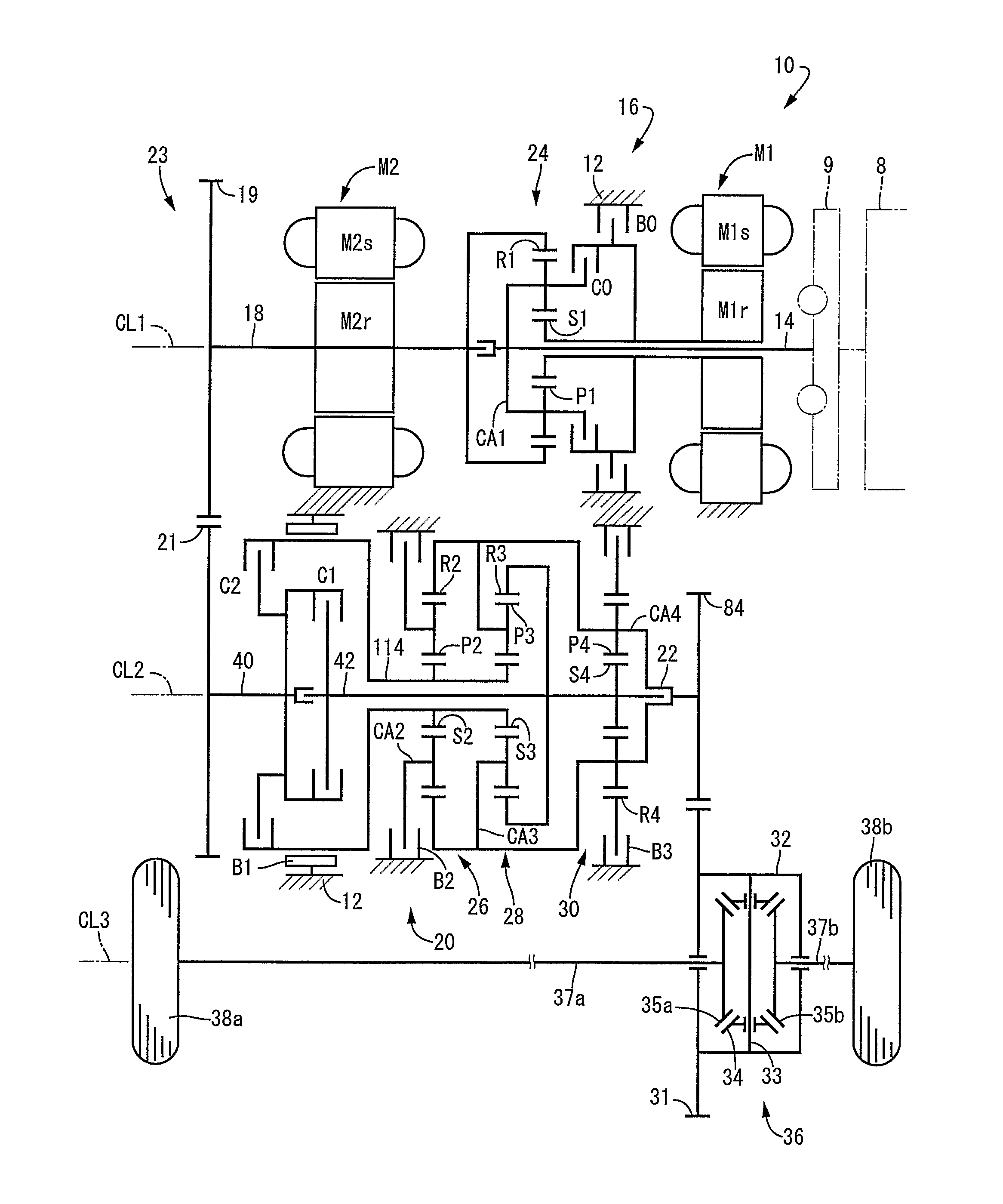
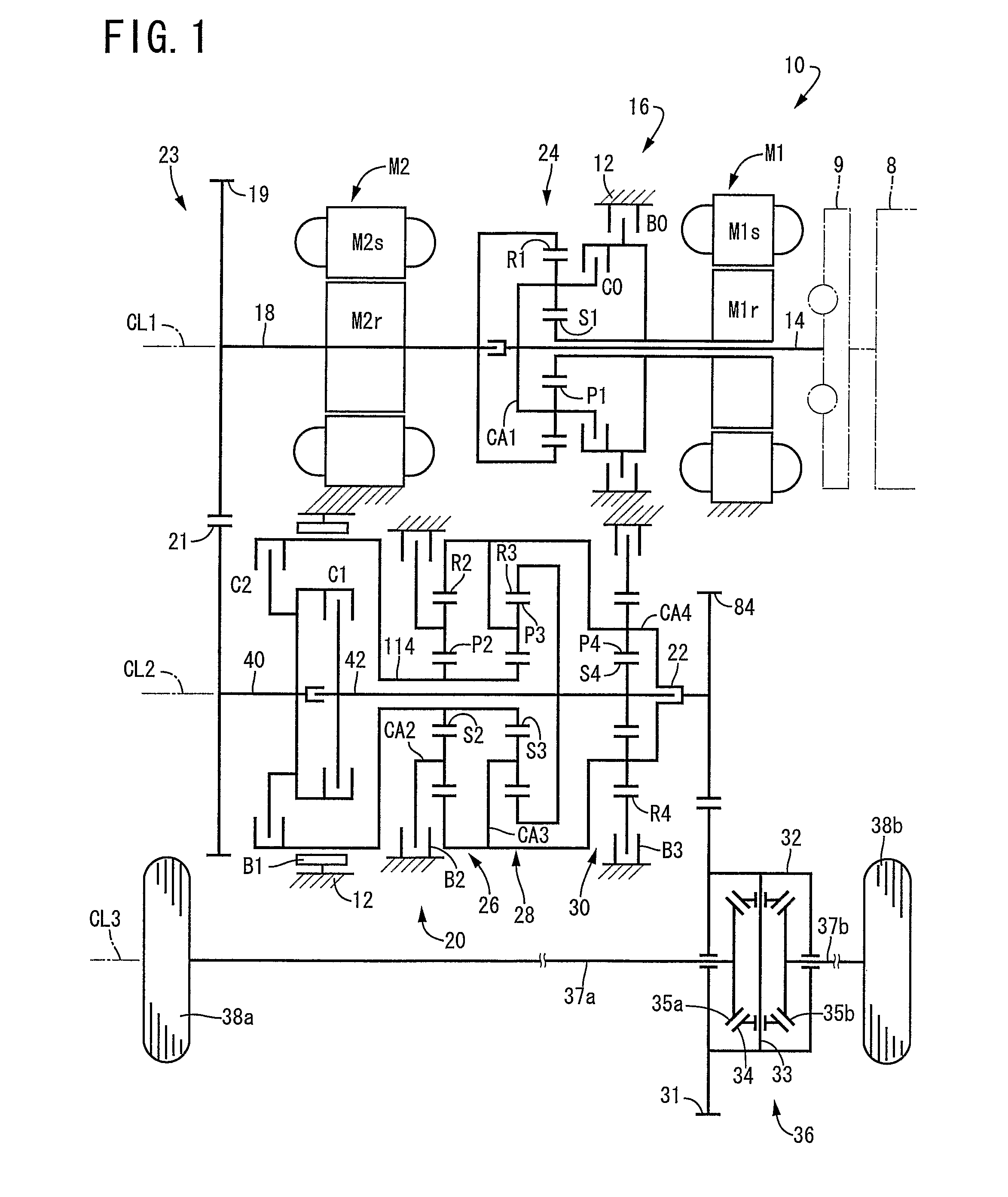
[0041]Referring first to the schematic view of FIG. 1, there is shown a drive system 10 for a hybrid vehicle, which is constructed according to one embodiment of this invention. The drive system 10 shown in FIG. 1 includes: an engine 8; a transaxle housing 12 (hereinafter referred to simply as “housing 12”), which is a stationary member attached to the body of the vehicle; a pulsation absorbing damper (vibration damping device) 9; a first input shaft in the form of an input rotary member 14 connected to the engine 8 through the pulsation absorbing damper 9 and receiving an output of the engine 8 through the pulsation absorbing member 9; a first electric motor M1; a hydraulically operated differential limiting device in the form of a switching clutch C0 and a switching brake B0; a differential gear mechanism or differential portion in the form of a power distributing mechanism 16 connected to the input rotary member 14; a second input shaft in the form of a power transmitting member ...

embodiment 2

[0111]There will be described other embodiments of the present invention. In the following description of the other embodiments, the same reference signs as used in the first embodiment will be used to identify the functionally identical elements, redundant description of which is omitted.

[0112]Referring to the fragmentary cross sectional view of FIG. 19, there is shown a part of a vehicular drive system 186 according to the second embodiment of this invention. This drive system 186 is different from the drive system 10 of the first embodiment, only in that a drive linkage 188 is provided in place of the drive linkage 23. As shown in FIG. 19, the drive linkage 188 includes a drive sprocket 190, a driven sprocket 192, and a connecting belt 194 which is formed of a metal or resin and which connects the drive and driven sprockets 190, 192. The drive sprocket 190 is mounted on the axial end portion of the power transmitting member 18 through the connecting member 118 such that the drive...

embodiment 3

[0113]Referring next to the fragmentary cross sectional view of FIG. 20, there is shown a part of a vehicular drive system 196 according to the third embodiment of the invention. This drive system 196 is different from the drive system 10 of the first embodiment, in that the axial position of the engine 8 is opposite to that in the first embodiment, and in that an idler gear 200 is interposed between the differential drive gear 84 and the large-diameter gear 31 of the final reduction gear device 36. The idler gear 200 is rotatably supported by the first and second casing portions 12a, 12b, via bearings 198. In the present third embodiment, a fourth axis CL4 is provided between and in parallel to the second and third axes CL2, CL3, and the idler gear 200 is supported rotatably about the fourth axis CL4, in meshing engagement with the differential drive gear 84 and the large-diameter gear 31 of the final reduction gear device 36. The idler gear 200 transmits a rotary motion from the d...


PUM


Abstract

A vehicular drive system accommodated in a housing and including a first input shaft that receives a vehicle drive force generated by a vehicle drive power source, and a differential mechanism operable to distribute the vehicle drive force received from the first input shaft to a first electric motor and a second input shaft. The first and second input shafts are disposed coaxially with a first axis such that the second input shaft is disposed downstream of the first input shaft. The first input shaft is rotatably supported by a first support portion provided on the housing and an axial end portion of the second input shaft, and the second input shaft is rotatably supported by a third support portion and a fourth support portion that are provided on the housing.

Description

TECHNICAL FIELD[0001]The present invention relates to a vehicular drive system including a first electric motor, a differential portion, a second electric motor and a transmission portion, and more particularly to techniques for reducing the axial dimension of the vehicular drive system and improving accuracy of assembling of the vehicular drive system.BACKGROUND ART[0002]There is known a vehicular drive system including a first electric motor, a differential portion, a second electric motor, and a transmission portion. JP-2003-301731A discloses an example of such a drive system for use on a hybrid vehicle. In the hybrid vehicle drive system disclosed in this publication, the first electric motor, differential portion, second electric motor and transmission portion are disposed coaxially with each other, such that they are arranged in the axial direction of the drive system in the order of description. Accordingly, the required axial dimension and width dimension of this vehicular d...

Claims


Application Information

Patent Timeline
Patent Type & Authority Patents(United States)
IPC IPC(8): F16H3/72F16H57/02B60K6/26B60K6/365B60K6/40B60K6/405B60K6/445B60K6/547B60K17/04B60L50/16F16H48/06F16H48/20F16H48/295F16H48/32F16H57/021F16H57/023F16H57/031
CPCB60K6/365B60K6/40B60K6/445F16H3/728F16H57/0037F16H57/021B60K1/02Y10T74/2186F16H2037/0873F16H2200/0043F16H2200/0047F16H2200/2007F16H2200/2023Y02T10/6239B60L7/26B60L15/2009B60L15/2036B60L15/2054B60L2220/42B60L2240/12B60L2240/507Y02T10/72B60L50/16Y02T10/62Y02T10/64Y02T10/7072Y02T10/70
Inventor TABATA, ATSUSHIMIYAZAKI, TERUFUMIKAMADA, ATSUSHITAGA, YUTAKA
Owner TOYOTA JIDOSHA KK
Why Eureka
Try Eureka