Check patentability & draft patents in minutes with Patsnap Eureka AI!

Decoding device

a decoding device and a technology for coding instruments, applied in the direction of code conversion, instruments, coding, etc., can solve the problems of data error, inability to completely reduce to zero,

Inactive Publication Date: 2011-08-02
MITSUBISHI ELECTRIC CORP
View PDF15 Cites 4 Cited by
  • Summary
  • Abstract
  • Description
  • Claims
  • Application Information

AI Technical Summary

Benefits of technology

The present invention provides a decoding device that can recover from errors in decoding video frames. The device includes error recovery means that monitor the decoding completion signal and issue a reset signal to recover the operation of the image decoder if decoding is not completed within a predetermined time. This ensures that even if there are errors in the decoded data, the image decoder can be recovered and the next video frame can be subjected to decoding processing. The device can also detect errors or loss of data in the received data and prevent erroneous data from being transmitted to the image decoder. Additionally, the device can record or output information indicating whether or not the video frame can be normally decoded by the image decoder, and extract embedded electronic watermark to determine whether or not decoding is performed normally.

Problems solved by technology

However, an error rate cannot be completely reduced to zero, so an error remains in the data.

Method used


Image

  • Decoding device
  • Decoding device
  • Decoding device

Examples


embodiment 1

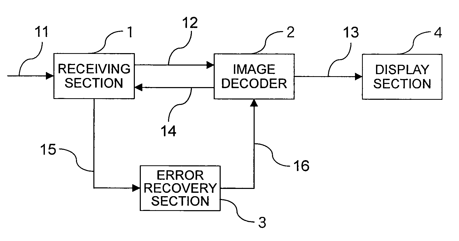
FIG. 1 is a block diagram showing a structure of a decoding device according to Embodiment 1 of the present invention. The decoding device shown in FIG. 1 includes a receiving section 1 for receiving encoded data 11 from a network or a storage medium, an image decoder 2 serving as a decoding means for decoding encoded data 12 from the receiving section 1, an error recovery section 3 for causing the image decoder 2 to operate again, and a display section 4 for displaying an image obtained by decoding by the image decoder 2 on a display, a projector, or the like.

Next, an operation will be described.

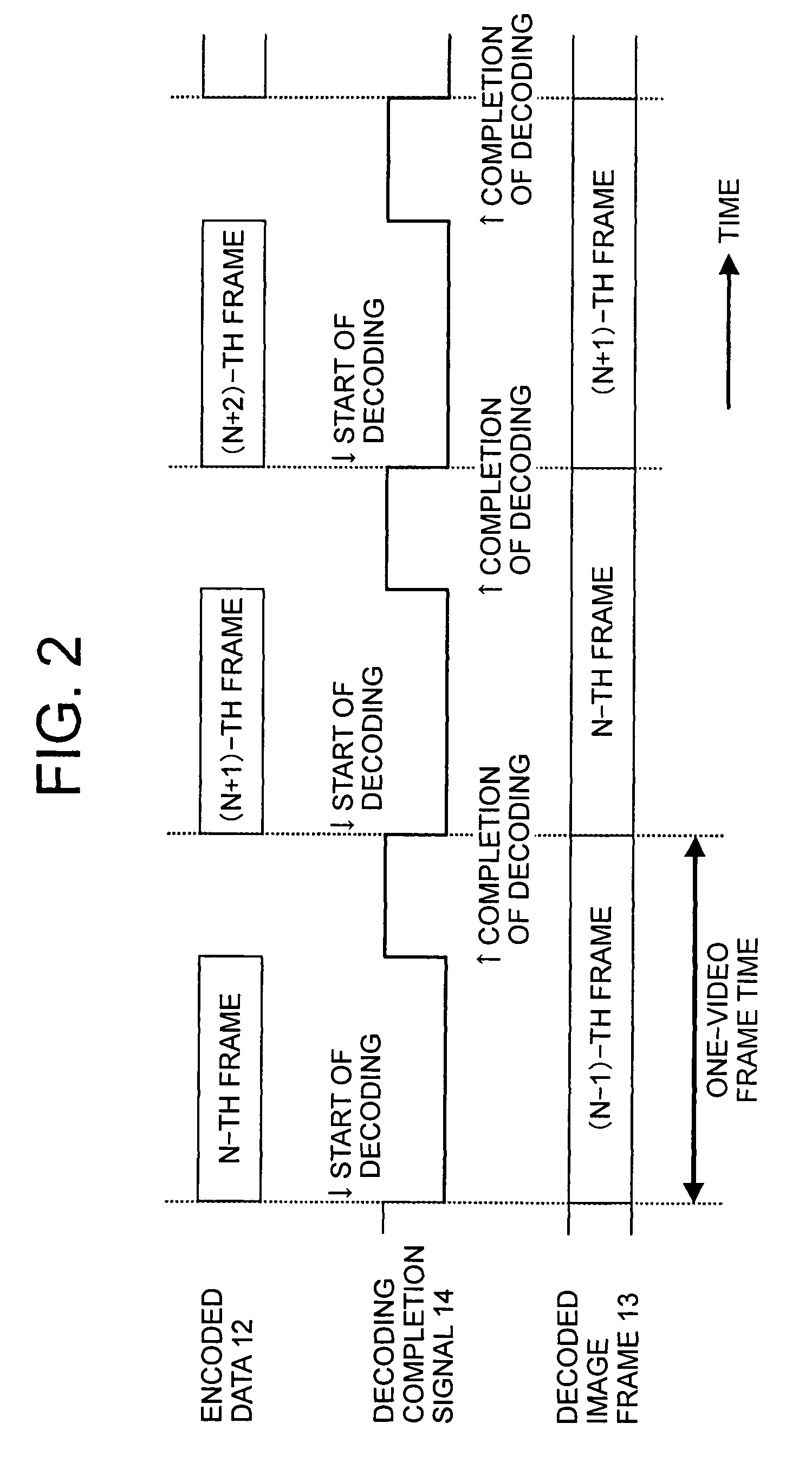
The encoded data 11 from a network or a storage medium such as a hard disk is inputted to the receiving section 1 and temporarily buffered in a memory or the like in an inner portion of the receiving section 1. The encoded data 12 corresponding to a video frame from the receiving section 1 is read out and inputted to the image decoder 2. A decoded image frame 13 obtained by decoding by the ...

embodiment 2

When the error of the encoded data 11 or a data loss thereof is detected by the receiving section 1 described in Embodiment 1, the error signal 15 can be generated without outputting the encoded data 12 of a video frame including the error or the data loss to the image decoder 2.

FIG. 4 is a block diagram showing an example of an internal structure of the receiving section 1.

The receiving section 1 shown in FIG. 4 includes a data check section 21 for detecting the data loss of the inputted encoded data 11 or the error thereof, an encoded data sending section 22 for outputting the encoded data 12 corresponding to a video frame based on the input of error-free encoded data which is inputted through the data check section 21, an error signal generating section 23 for generating the error signal 15 based on a detection signal outputted from the data check section 21 when the error of the encoded data 11 is detected and a signal outputted from a decoding completion detection section 24 wh...

embodiment 3

In Embodiment 3, the method of extracting the electronic watermark from the decoded image data is described. When irreversible encoding is performed in the encoding process, the original image data is reconstructed, so the electronic watermark for authenticity verification cannot be extracted. However, when the embedding of the electronic watermark is used for an encoded domain of image data (for example, embedding of watermark data for DCT coefficients), the same effect can be obtained.

According to Embodiment 3, the image decoder 2 includes the electronic watermark extraction section 33 for outputting the decoding completion signal to the receiving section 1 based on the extraction of the electronic watermark embedded in the decoded image. The electronic watermark for authenticity verification is extracted from the decoded image. Therefore, the watermark information can be correctly extracted, so the normal completion of decoding can be verified.

The summary of the invention is as f...


PUM


Abstract

Even when erroneous encoded data is inputted to a decoding device, the decoding device is recovered during one video frame period including a video frame time of the inputted data to enable decoding processing on a next video frame. The decoding device includes: a receiving section (1) for receiving encoded data (11) to output the encoded data corresponding to a video frame, outputting encoded data of a next frame in response to a decoding completion signal (14) to be received, and for transmitting an error signal (15) when the decoding completion signal is not received during a predetermined time; an image decoder (2) for decoding the encoded data (12) from the receiving section (1), transmitting the decoding completion signal (14) to the receiving section (1) when decoding is completed, and for stopping decoding processing in response to a reset signal (16) to be received; and an error recovery section (3) for outputting the reset signal (16) to the image decoder (2) when the error signal (15) is received.

Description

TECHNICAL FIELDThe present invention relates to a decoding device for decoding encoded image data and displaying the image data.BACKGROUND ARTIn recent years, along with rapid advances of digital image compression (encoding) techniques represented by MPEG and JPEG, it has become possible to efficiently transmit and receive a high-quality video image with a small information amount in real time. Even in a case of transmission of image data, an advancement of a digital modulation and demodulation technique enables high-speed digital communications using a satellite or an optical fiber. In addition, even in storage media, a large-capacity hard disk, a large-capacity DVD, and the like have been developed, and environments for a digital image to be transmitted or stored are being provided.Encoded data (bit stream, bit string) compressed at high efficiency is sensitive to an error, so the data is protected by an error correction technique against a transmission line error or a read error ...

Claims


Application Information

Patent Timeline
Patent Type & Authority Patents(United States)
IPC IPC(8): H03M13/00H04L1/00H04N1/387H04N19/00H04N19/102H04N19/134H04N19/166H04N19/423H04N19/44H04N19/46H04N19/467H04N19/625H04N19/65H04N19/67H04N19/70H04N19/89H04N19/895
CPCH04N19/00H04N19/89H04N19/467H04N19/44
Inventor KATOU, YOSHIAKIASAI, KOUTAROUMURAKAMI, TOKUMICHI
Owner MITSUBISHI ELECTRIC CORP
Features
  • R&D
  • Intellectual Property
  • Life Sciences
  • Materials
  • Tech Scout
  • Unparalleled Data Quality
  • Higher Quality Content
  • 60% Fewer Hallucinations
Learn More