Roughing insert and roughing end mill

a technology of end mill and insert, which is applied in the direction of turning machine accessories, shaping cutters, manufacturing tools, etc., can solve the problems of insufficient fragmentation of chips and reduce resistance, and achieve the effects of preventing any conspicuous deterioration in the surface roughness of processing surfaces, reducing cutting resistance, and improving chip processingability

Active Publication Date: 2011-08-09
MITSUBISHI MATERIALS CORP
View PDF17 Cites 14 Cited by
  • Summary
  • Abstract
  • Description
  • Claims
  • Application Information

AI Technical Summary

Benefits of technology

[0021]In this manner, according to the roughing insert of the present invention, it is possible to achieve a reduction in cutting resistance and an improvement in chip processability by means of a waveform cutting edge formed on an insert body. In addition, in a portion of a waveform cutting edge in which the amplitude of the wave has been made smaller, even if the worn insert is mounted by mistake, it is possible to prevent any conspicuous deterioration in the surface roughness of the processing surface of a work piece being formed. Accordingly, according to a roughing insert in which this insert has been mounted, it is not necessary to set a substantial allowance or the like in the finishing processing in portions of the subsequent steps, and it becomes possible to achieve efficient processing.

Problems solved by technology

Because of this, it is not possible to sufficiently fragment the chips and reduce resistance, or to soften the bite impact of the cutting edges.

Method used


Image

  • Roughing insert and roughing end mill
  • Roughing insert and roughing end mill
  • Roughing insert and roughing end mill

Examples


Embodiment Construction

Problems to be Solved by the Invention

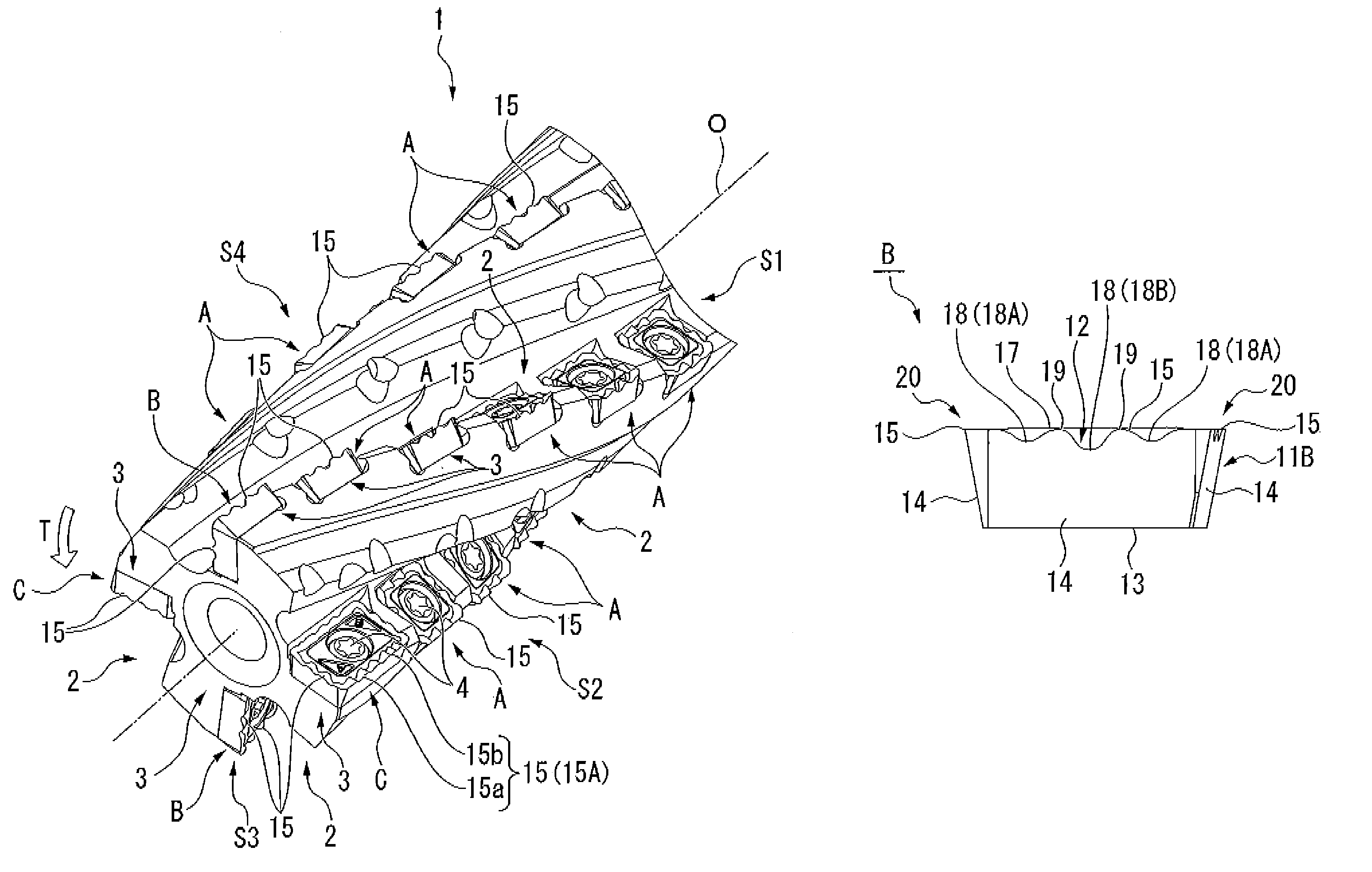
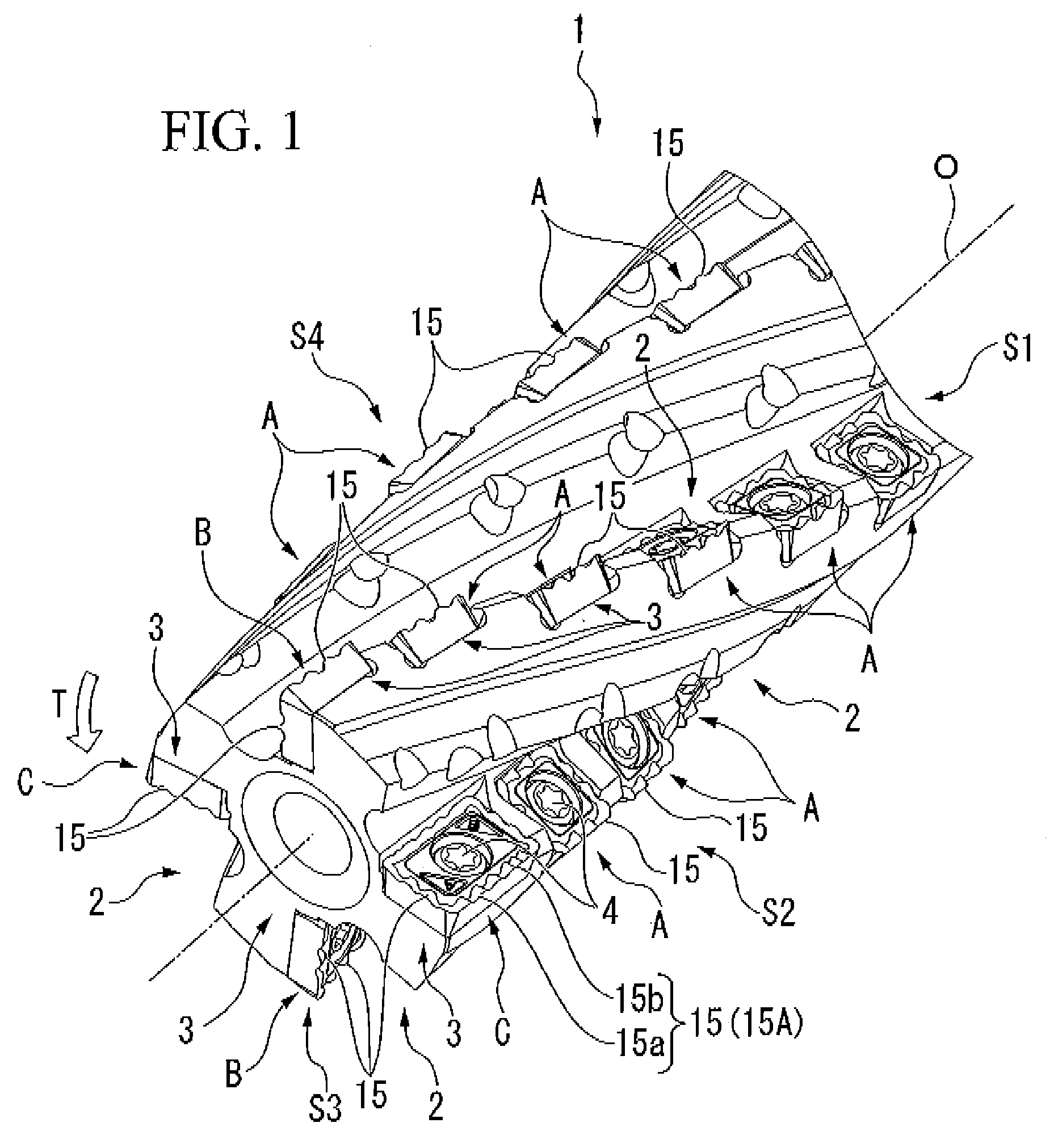
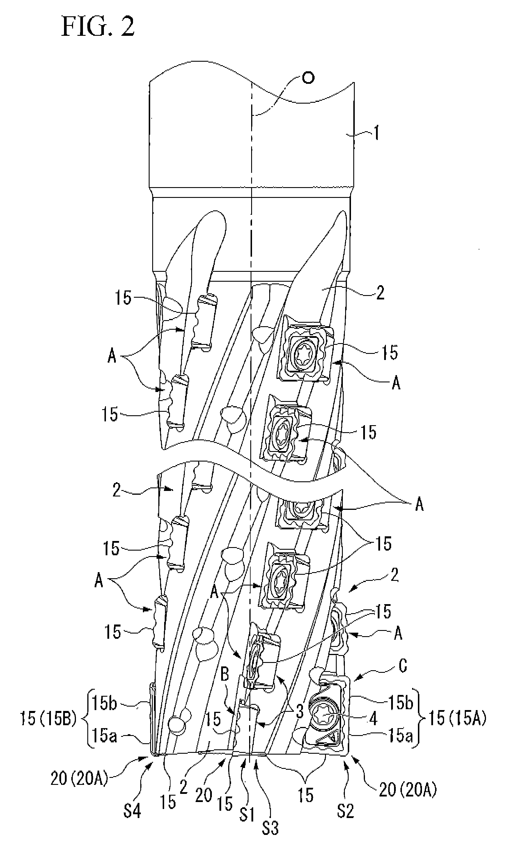
[0008]However, in a roughing end mill fitted with inserts in which waveform cutting edges are formed such as that described in Patent document 3, if the rotation trajectories of overlapping waveform cutting edges of inserts which are adjacent in the circumferential direction match each other, then identical waveform shapes become transferred onto the processing surface of a work piece. Because of this, it is necessary to make the rotation trajectories different by offsetting the phases thereof or the like. In this case, even if the second and following inserts from the distal end of each chip removal groove are formed as a single type having the same shape and size and having uniform waveform cutting edge phases, the rotation trajectories can be made different from each other by offsetting in the axial direction the mounting seats where these inserts are mounted which are adjacent in the circumferential direction, so that, on the rotation trajec...


PUM

PropertyMeasurementUnit
angleaaaaaaaaaa
obtuse angleaaaaaaaaaa
wavelengthaaaaaaaaaa

Abstract

This roughing insert is provided with an insert body, and a waveform cutting edge which is formed on an intersecting ridge line portion between a rake face and a flank face of the insert body, and which undulates along this intersecting ridge line portion. The waveform cutting edges are formed such that a portion thereof has a smaller wavelength than the remaining portion thereof.

Description

CROSS-REFERENCE TO PRIOR APPLICATION[0001]This is the U.S. National Phase Application under 35 U.S.C. §371 of International Patent No. PCT / JP2007 / 067851 filed Sep. 13, 2007, which claims the benefit of Japanese Patent Application No. 2006-248174 filed Sep. 13, 2006 and Japanese Patent Application No. 2006-295907 filed on Oct. 31, 2006. The International Application was published in Japanese on Mar. 20, 2008 as International Patent Application No. WO / 2008 / 032788 under PCT Article 21(2), and all preceding applications are incorporated herein in their entirety.TECHNICAL FIELD[0002]The present invention relates to a roughing insert which is provided with a waveform cutting edge and is used to perform rough processing on a piece of work, and to a removable insert type of roughing end mill which has this roughing insert mounted on an outer circumference of an end mill body.BACKGROUND ART OF THE INVENTION[0003]These roughing end mill equipped with replaceable inserts have been proposed, fo...

Claims


Application Information

Patent Timeline
Patent Type & Authority Patents(United States)
IPC IPC(8): B26D1/00B23C5/02
CPCB23C5/109B23C5/207B23C2200/206B23C2210/66B23C2220/60Y10T407/1924Y10T407/192Y10T407/235Y10T407/1958Y10T407/1936Y10T407/23B23C5/202B23C5/205
Inventor HORIIKE, NOBUKAZUKITAJIMA, JUN
Owner MITSUBISHI MATERIALS CORP
Why Eureka
Try Eureka