

Lubricating oil supply facility and lubricating oil supply method
A technology for supplying equipment and lubricating oil, which is used in the direction of mechanical equipment, engine lubrication, metal processing equipment, etc.
- Summary
- Abstract
- Description
- Claims
- Application Information
AI Technical Summary
Problems solved by technology
Method used
Image

Examples
Embodiment
[0131] The control of the lubricating oil supply amount is performed in the fifth stand of the hot finish rolling mill consisting of seven rolling mills from the first stand to the seventh stand. The steel to be rolled passes sequentially from the first station to the seventh station, and is rolled in each station. The steel to be rolled is general low-carbon steel, and the steel with a plate thickness of 32mm on the first entry side is rolled in such a way that the thickness of the exit side of the seventh station is changed to 2.3mm. As the steel material to be rolled, a steel material having a plate width of 1820 mm to 1940 mm is used.
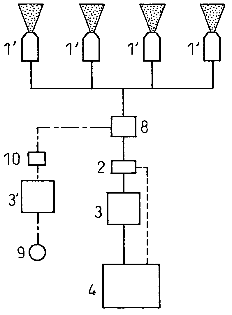
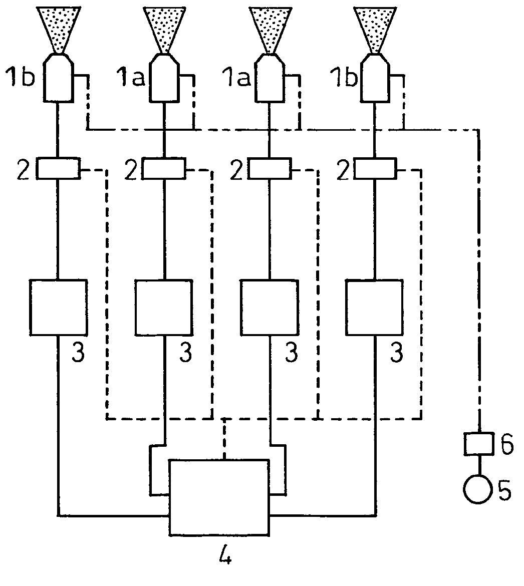
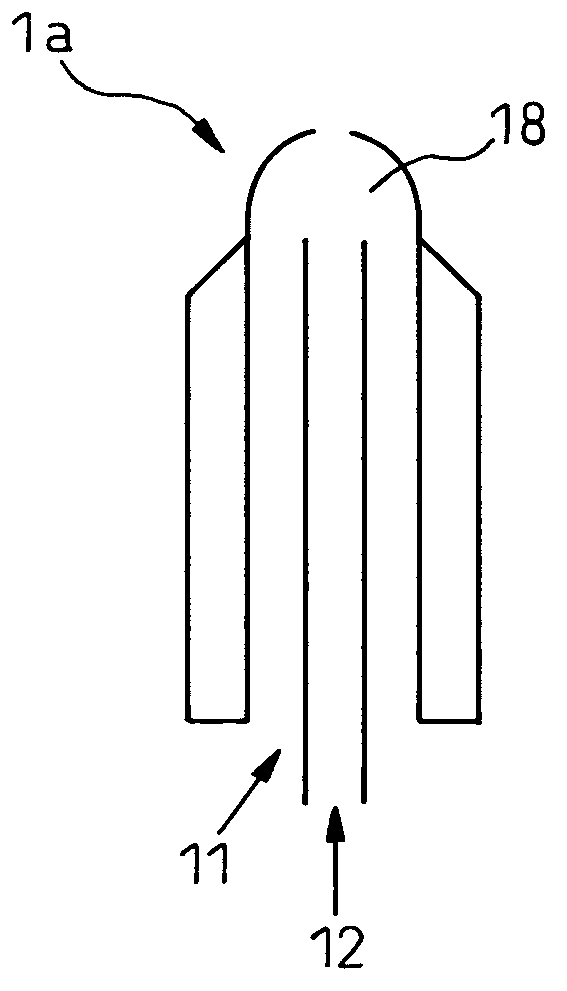
[0132] A header in which spray nozzles are arranged in the axial direction of the roll is provided, and a gear pump capable of individually setting the supply amount of lubricating oil is connected to each spray nozzle. For nozzles, such as Figure 5 As shown, the spray nozzle configuration was carried out. As the roll, a roll whose roll...
PUM
| Property | Measurement | Unit |
|---|---|---|
| Kinematic viscosity | aaaaa | aaaaa |
Abstract
Description
Claims
Application Information