Heat treatment apparatus

a technology of heat treatment apparatus and heat treatment chamber, which is applied in the direction of lighting and heating apparatus, applications, manufacturing tools, etc., can solve the problems of extreme deterioration of efficiency, extreme deterioration of energy efficiency required for heating, and high temperature resistance, and achieve low maintenance costs and high throughput. , the effect of high temperatur

Inactive Publication Date: 2012-11-15
HITACHI HIGH-TECH CORP
View PDF11 Cites 5 Cited by
  • Summary
  • Abstract
  • Description
  • Claims
  • Application Information

AI Technical Summary

Benefits of technology

[0018]According to the embodiments of the present invention, it is possible to provide a heat treatment apparatus in which thermal efficiency is high, a maintenance expense is low, a throughput is high, surface roughness of a treated su

Problems solved by technology

The first problem is thermal efficiency.
Therefore, since the amount of radiation increases in proportion to the fourth root of a temperature, when a heated region is large, energy efficiency required for heating deteriorates extremely.
Further, since a heated sample is distant from a heat source (heater) by the double tube, a heater unit has a high temperature equal to or higher than the heated sample, thereby significantly deteriorating efficiency.
In addition, for the same reason, the heat capacity of the heated region is significantly increased and rising or falling of the temperature takes time.
Therefore, as a time period from carry-in to carry-out of a heated sample increases, a throughput deteriorates and further, a time period in which the heated sample stays under a high-temperature atmosphere increases, thereby increasing surface roughness of the heated sample to be described below.
The second problem is wastefulness of a furnace materi

Method used


Image

  • Heat treatment apparatus
  • Heat treatment apparatus
  • Heat treatment apparatus

Examples


first embodiment

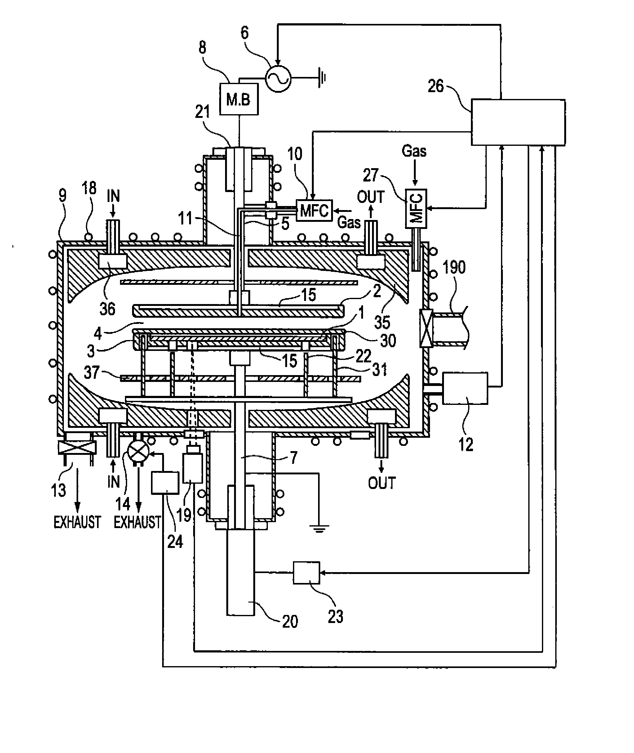
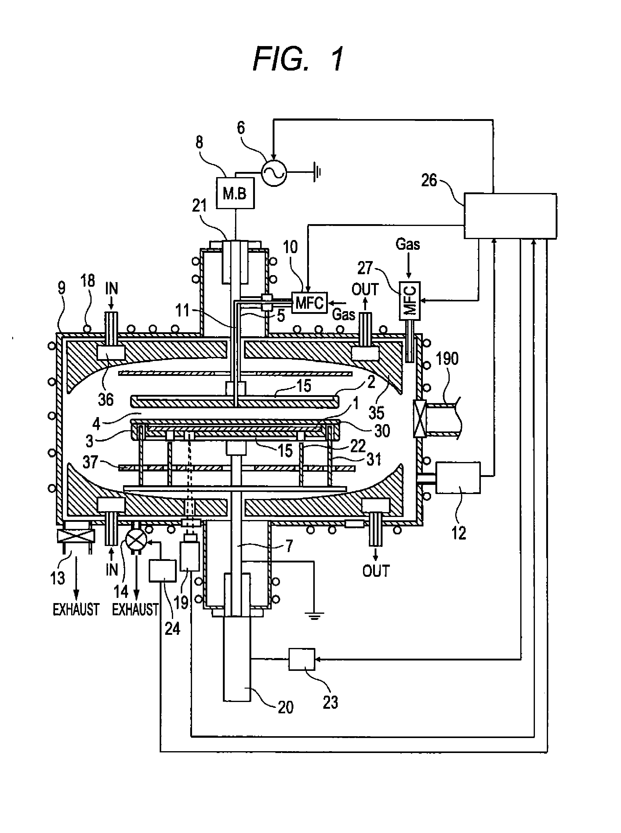
[0028]A basic configuration of a heat treatment apparatus according to an embodiment of the present invention will be described with reference to FIG. 1. A heated sample 1 is installed on a first lower electrode 3 and a second lower electrode 30 is installed on the heated sample 1. Further, since the second lower electrode 30 contacts the first lower electrode 3 on the outer periphery thereof, the second lower electrode 30 does not contact the heated sample 1. In the embodiment, as the heated sample 1, a 4-inch (9100 mm) SiC is used. As an upper electrode 2 and the first lower electrode 3 have a diameter of 120 mm and a thickness of 5 mm. Meanwhile, the second lower electrode 30 has a diameter of 120 mm and a thickness of 1 mm. The thickness of the second lower electrode 30 may be determined considering rigidity and a heat capacity. The upper electrode 2, and the first lower electrode 3, and the second lower electrode 30 are used to deposit SiC onto the surface of a graphite substra...

second embodiment

[0066]FIG. 6 shows a case in which the heated sample 1 is placed even in the upper electrode as well as the lower electrode. In order to install the heated sample 1 in the hollow upper electrode 33, the heated sample is placed on the wall of the hollow of the hollow upper electrode 33 at the side of the gap 4 where plasma is formed. In order to use the heated sample moving-up and down mechanism used in the lower electrode, a hole is formed at the gap 4 of the hollow upper electrode 33, such that the heating uniformity is deteriorated. Herein, a protrusion 34 is installed in the hollow of the hollow upper electrode 33, the heated sample 1 is placed above the protrusion 34 to form the gap between the inner wall of the hollow upper electrode 33 and the heated sample 1, and the heated sample 1 can be carried in and out by the transport arm. The heated sample 1 locally contacts the protrusion 34 of the upper electrode, but a heating mechanism is primarily performed by heated gas and the ...


PUM

PropertyMeasurementUnit
Temperatureaaaaaaaaaa
Lengthaaaaaaaaaa
Temperatureaaaaaaaaaa

Abstract

Provided is a heat treatment apparatus in which a heat treatment apparatus in which the thermal efficiency is high, the maintenance expense is low, the throughput is high, the surface roughness of a sample can be reduced, and the discharge uniformity is excellent, although the heat treatment is performed at 1200° C. or more.
A heat treatment apparatus includes: parallel planar electrodes; a radio-frequency power supply generating plasma by applying radio-frequency power between the parallel planar electrodes; a temperature measuring section measuring the temperature of a heated sample; and a control unit controlling an output of the radio-frequency power supply, wherein at least one of the parallel planar electrodes has a space where the heated sample is installed, therein, and heats the sample in the electrode by the plasma generated between the parallel planar electrodes.

Description

CLAIM OF PRIORITY[0001]The present application claims of priority from Japanese patent application JP 2011-104841 filed on May 10, 2011, the content of which is hereby incorporated by reference into this application.FIELD OF THE INVENTION[0002]The present invention relates to a heat treatment apparatus that performs activation annealing or defect repairing annealing and oxidation of the surface after doping impurity to a semiconductor substrate.BACKGROUND OF THE INVENTION[0003]In recent years, as substrate materials of a power semiconductor device, the introduction of new materials having a wideband gap, such as silicon carbide (SiC) has been expected. SiC, the wideband gap semiconductor has physical properties more excellent than silicon (Si), such as a high insulation breakdown field, a high saturated electron velocity, and a high thermal conductivity. The high insulation breakdown field material enables element thinning or high-concentration doping and causes a high pressure-resi...

Claims


Application Information

Patent Timeline
IPC IPC(8): B23K9/00
CPCC23C16/46H01L21/324C23C16/325C23C16/5096H01L29/1608H01J37/32724H01J37/32935H01L21/67069H01L21/6719H01J37/32091H01L21/3247
Inventor MIYAKE, MASATOSHIYOKOGAWA, KEN'ETSU
Owner HITACHI HIGH-TECH CORP
Why Eureka
Try Eureka