
Mobile split palletizer

a palletizer and mobile technology, applied in the field of articles handling systems, can solve the problems of requiring significant worker interaction, reducing the delivery cost of conventional manual palletizers, and reducing the delivery cost of goods

Inactive Publication Date: 2011-08-09
GRAHAM PACKAGING CO LP
View PDF23 Cites 21 Cited by
  • Summary
  • Abstract
  • Description
  • Claims
  • Application Information

AI Technical Summary

Benefits of technology

The present invention provides a modular split palletizer for loading layers of articles on stackable pallets. The palletizer has three sections that can be disassembled, moved individually and independently, and re-assembled at a new location to form the complete palletizer. The invention also provides a method of relocating a modular split palletizer from one location to another. The technical effects of the invention include improved flexibility, efficiency, and ease of relocation.

Problems solved by technology

The transfer and distribution of goods is expensive in both time and manpower, and contribute to the cost of goods.
Conventional manual palletizers require significant worker interaction.
For example, it is challenging to retain employees in low-wage, low-prestige positions such as those encompassing manual palletizing.
The United States Occupational Safety and Health Administration (OSHA) standards regarding weight and repetitive motion limitations can be difficult to follow.
And job-related back injuries are costly and can increase a company's insurance premiums.
Third, production speeds in some packaging lines are past the point where articles can be hand stacked.
First, low-level traditional palletizers intake a continual flow of articles at ground level.
Although fast, low-level traditional palletizers are not best for fragile items.
Second, high-level traditional palletizers are similar to their low-level counterparts.
They do not handle fragile items well, but they intake and load a continual flow of articles quickly.
Robotic palletizers often cost more than traditional palletizers.
Palletizers typically are designed to stack as many as 30-40 boxes or other articles on a relatively large pallet Therefore, these systems must be relatively large to accommodate fully stacked pallets—so large, in fact, that they are typically fixed in one location and are not easily moved.
Stacks of pallets instead are conveyed to and from the article handling system by dedicated conveyors, which further increase the space requirements of the system.
Another problem associated with standard palletizers is that they are poorly suited for rapidly handling a relatively small numbers of articles.
Consequently, palletizers used in these applications must routinely handle partially loaded pallets with an over-sized system that operates at less than one-third to one-half of its capacity at a considerable waste of space and resources.
In summary, conventional palletizers are typically mounted directed to the floor of the plant, are large in size, and may cost on the order of $800,000.
Quality palletizers last a long time and refurbish well.

Method used


Image

  • Mobile split palletizer
  • Mobile split palletizer
  • Mobile split palletizer

Examples


Embodiment Construction

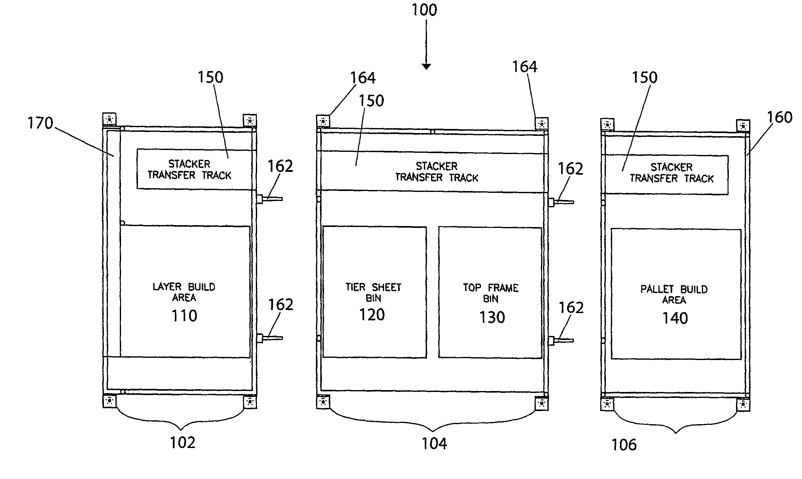
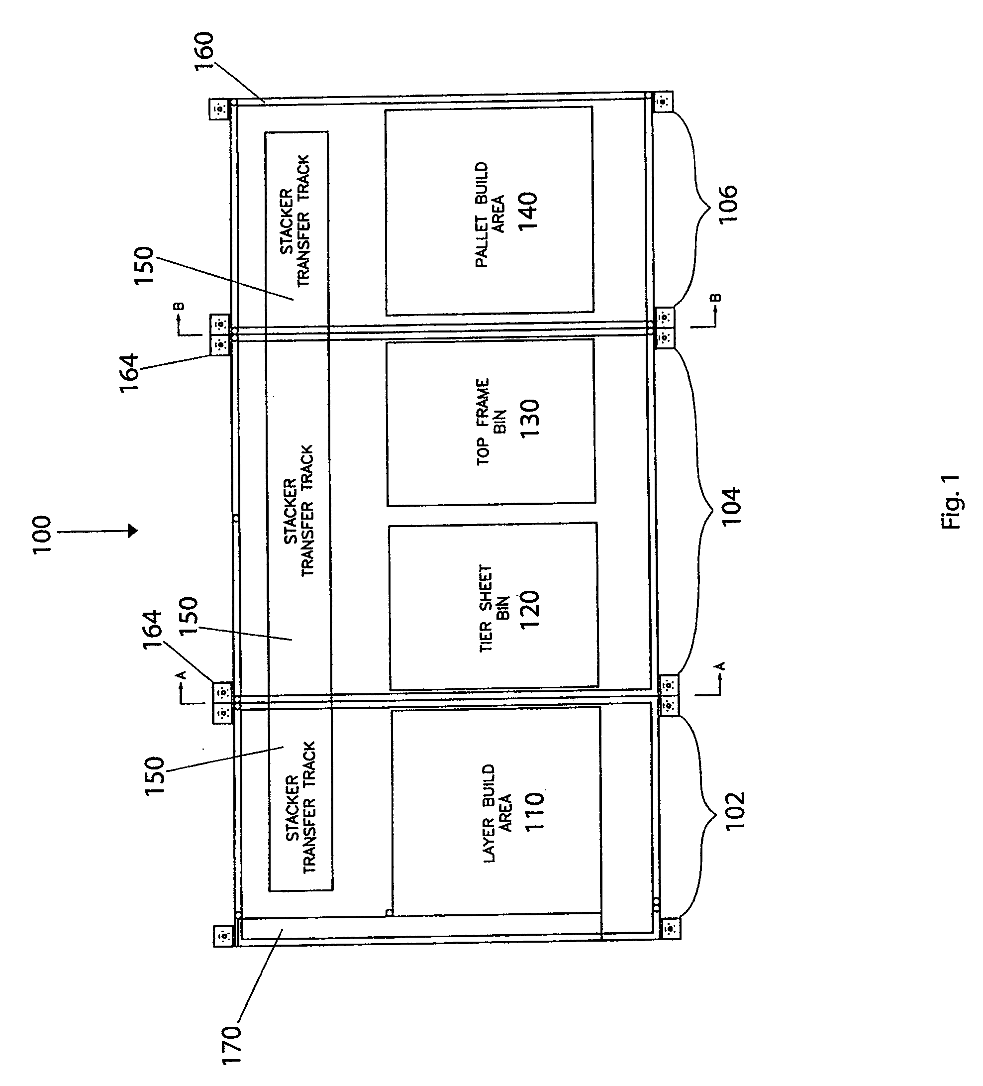
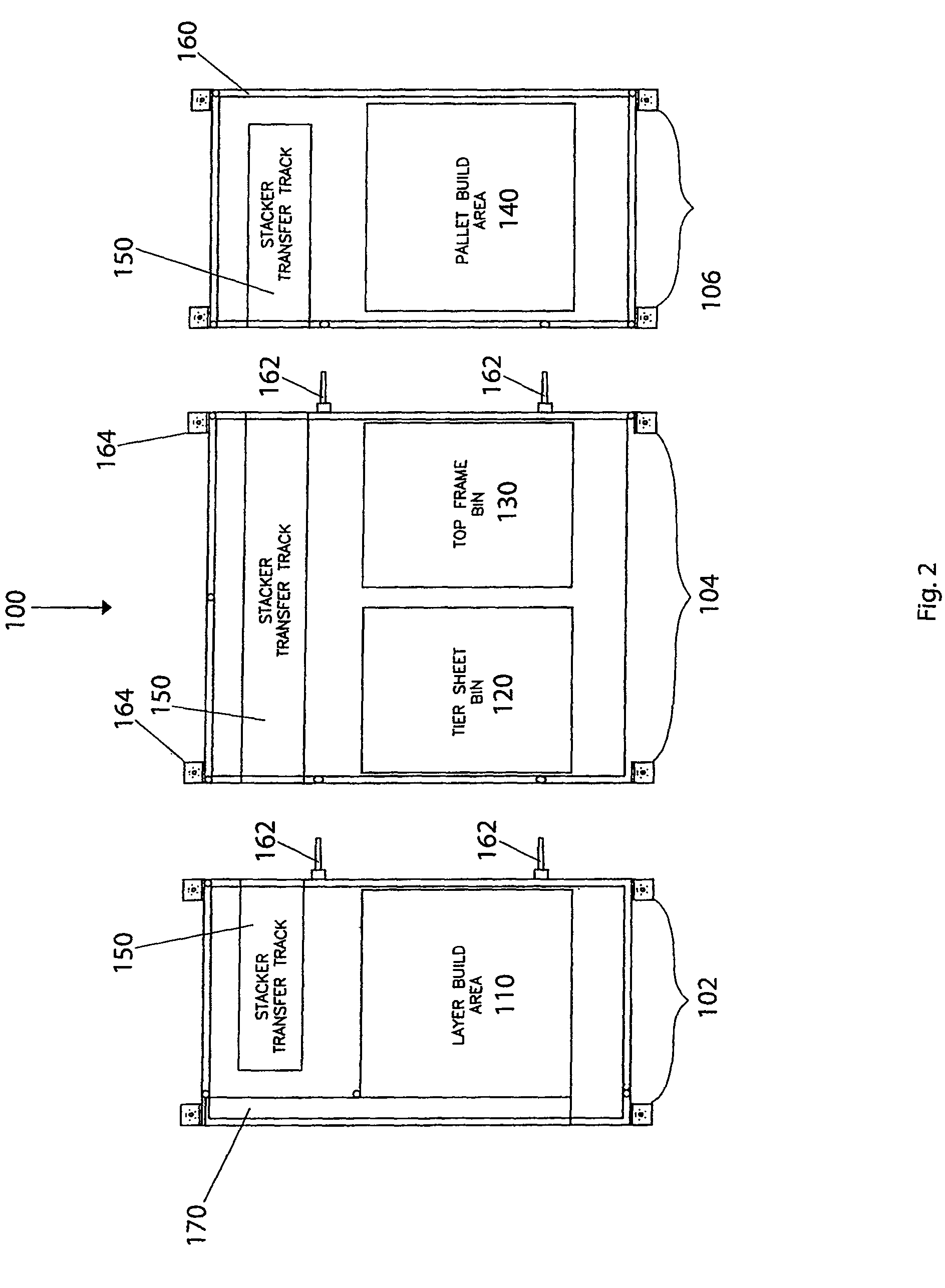
[0023]Referring now to the drawing, in which like reference numbers refer to like elements throughout the various figures that comprise the drawing, FIG. 1 shows the modular split palletizer 100, in a top schematic view, according to the present invention. The palletizer 100 includes a layer build area 110, a tier sheet bin 120, a top frame bin 130, a pallet build area 140, a stacker transfer track 110, and a sub-base or frame 160. The frame 160 is preferably made of steel.

[0024]A conveyor 170 delivers the articles 10 to the palletizer 100. The conveyor 170 may be included as part of the palletizer 100. Alternatively, the conveyor 170 may be a component separate from the palletizer 100. The conveyor 170 conveys articles 10 either singly or in single-layer patterns to the palletizer 100. The conveyor 170 may be a belt, chain, or powered roller conveyor, and may be an endless conveyor. The conveyor 170 delivers the articles 10 specifically to the layer build area 110 of the palletizer...


PUM


Abstract

A modular split palletizer for loading layers of articles on stackable pallets. The palletizer has a frame supporting first, second, and third sections. The first section includes a layer build area and a first portion of a stacker transfer track. The second section includes a tier sheet bin, a top frame bin, and a second portion of the track. The third section includes a pallet build area and a third portion of the track. Each of the first, second, and third sections can be disassembled, moved individually and independently, and re-assembled at a new location to form the complete palletizer. Also disclosed is a method of relocating the modular split palletizer. With the palletizer at one location, the utilities connected to the palletizer are disconnected, the fasteners holding the sections together are released, and the sections are separated. The disassembled sections are moved to the new location and reassembled.

Description

TECHNICAL FIELD[0001]The present invention relates generally to article handling systems and, more particularly, to a method and apparatus for loading layers of articles on stackable pallets.BACKGROUND OF THE INVENTION[0002]The transfer and distribution of goods is expensive in both time and manpower, and contribute to the cost of goods. Pallets used in combination with the forklift have produced substantial economies in the movement of goods by providing many different goods with a similar interface, allowing mechanization and unitization of goods. Nevertheless, the pressure to reduce the cost of supplying goods continues to drive a search for improvements in distribution.[0003]Industrial article handling systems are well known for stacking layers of articles on a pallet. The articles may be cans, containers, bottles, cases, drums, crates, bags, boxes, and many other types of articles. Article handling systems that stack layers of articles on a pallet to load the pallet generally a...

Claims


Application Information

Patent Timeline
Patent Type & Authority Patents(United States)
IPC IPC(8): B65G57/24B65G57/00
CPCB65G57/00B65G57/24Y10S414/106
Inventor REICHLER, JOHN R.
Owner GRAHAM PACKAGING CO LP
Learn More