Hub for power transmission apparatus

a technology for power transmission apparatus and hub, which is applied in the direction of gearing elements, belts/chains/gearrings, hoisting equipment, etc., can solve the problems of reducing durability and the inability to increase the radial direction of the cylindrical portion of the hub b>29/b>, and achieves the effect of increasing the durability of the apparatus and less stress concentration

Active Publication Date: 2011-08-09
DENSO CORP
View PDF9 Cites 0 Cited by
  • Summary
  • Abstract
  • Description
  • Claims
  • Application Information

AI Technical Summary

Benefits of technology

The object of this invention is to solve the problem described above and provide a hub for use in a power transmission apparatus wherein there is less stress concentration between the cylindrical portion and the engaging portion, even if the reinforcing portions are protruded from the outer ring protrusions radially inward. Accordingly, it is possible to increase durability of the apparatus.
By adopting this means, stress and strain are prevented from being concentrated at the portion connected between the cylindrical portion (81) and the hub-side engaging portion (85), in addition to improved durability. As a result, the reinforcing portions (83c) can be bent radially inward, so that the spring constant of the elastic body can be reduced without reducing the diameter of the hub (77) or increasing the diameter of the hub (77) and the pulley (59).
According to another aspect of the invention, in order to solve the above-mentioned problem, there is provided a hub for use in the power transmission apparatus, wherein the reinforcing portions (83c) are formed at the peripheral ends of the protrusions (83b). The concentration of stress and strain can thus be further prevented, resulting in an improved durability.
As a result, the concentration of stress and strain on the portion between the cylindrical portion (81) and each reinforcing portion (83c) can be prevented for an improved endurance.
By adopting the aforementioned means, the stress and strain are prevented from being concentrated at the portion connected between the cylindrical portion (81) and the hub-side engaging portion (85) and the hub-side engaging portion (85), in addition to an improved durability.
As a result, the reinforcing portions (83c) can be bent radially inward, thereby producing substantially the same effect as the first aspect of the invention described above.

Problems solved by technology

However, due to space limitation, cylindrical portion 29 of hub 25 cannot be increased in the radial direction.
If the tongue-like reinforcing portions are bent inward, stress and strain are concentrated at the root of the cylindrical rubber portion of the engaging portion, and the strain would be further concentrated if the axial distance is shorten between the root and the reinforcing portion, thereby resulting in reduced durability.

Method used


Image

  • Hub for power transmission apparatus
  • Hub for power transmission apparatus
  • Hub for power transmission apparatus

Examples


Embodiment Construction

The embodiments of the invention are explained below with reference to FIGS. 1 to 3.

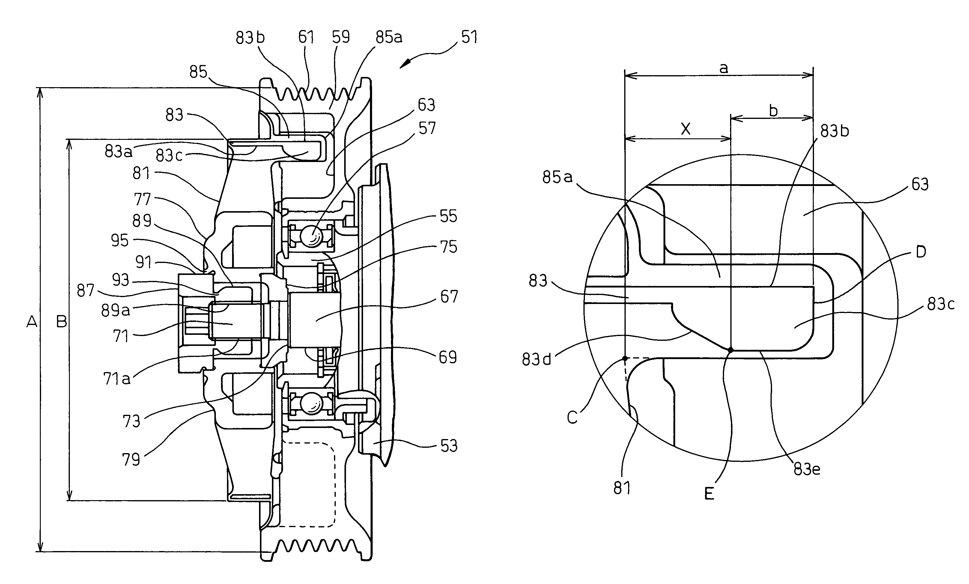
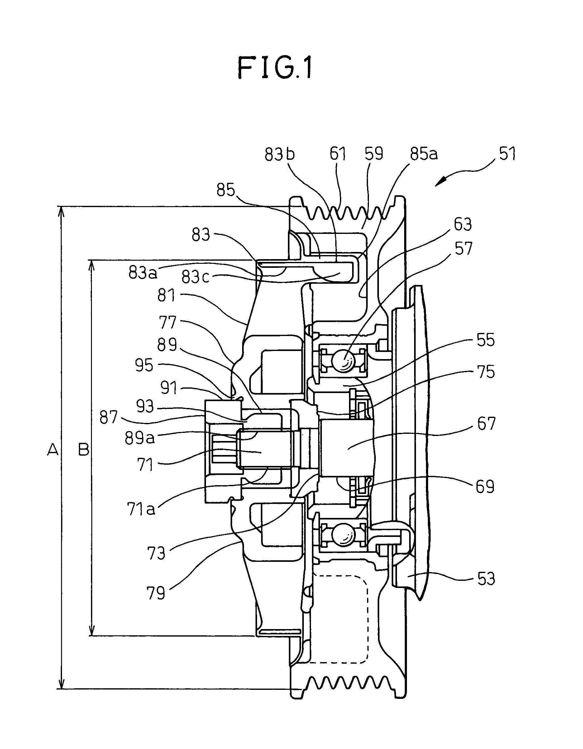
FIGS. 1 to 3 show power transmission apparatus 51 having a hub according to an embodiment of the invention. Power transmission apparatus 51 includes compressor housing 53. Cylindrical bearing support portion 55 is arranged on front side (left side in FIG. 1) of the housing 53. Pulley 59 is supported through radial bearing 57 on the outer periphery of bearing support portion 55. Belt grooves 61 are formed on the outer periphery of pulley 59, and the belt is wound along belt grooves 61 thereby to transmit the rotational torque from the vehicle engine or the like. The diameter A of pulley 59 is approximately 100 to 130 mm.

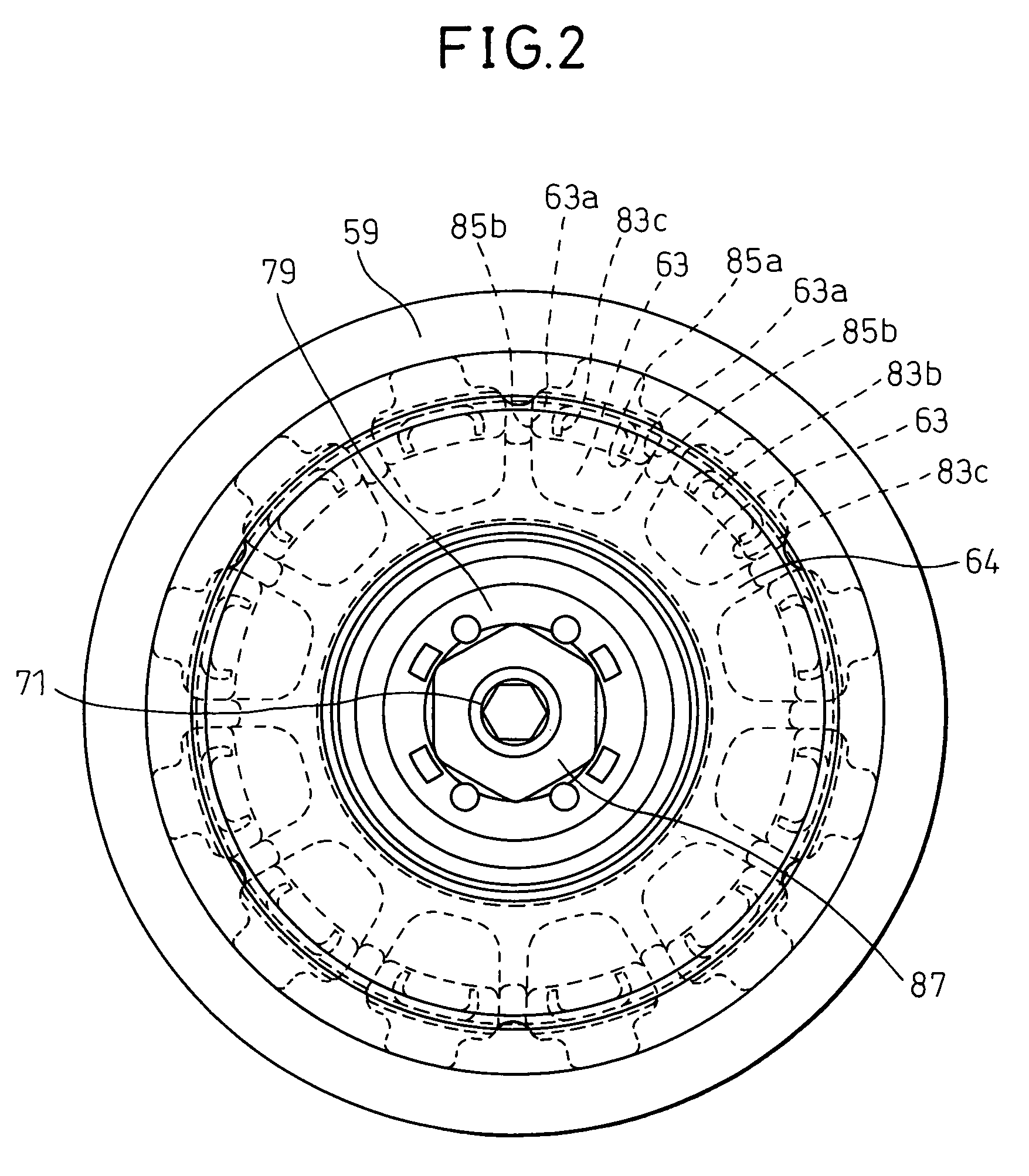
A plurality of pockets 63 are formed equidistantly along the peripheral direction on the front side of pulley 59. The side walls of pockets 63, which are peripherally opposed to each other, form pulley-side engaging surfaces 63a, and rib 64 is formed between each pair of adjoining pock...


PUM


Abstract

A hub for use in a power transmission apparatus comprises cylindrical portion 81 and outer ring 83 including a plurality of tongue-like reinforcing portions 83c each protruded radially inward from the peripheral end of the corresponding one of the plurality of protrusions 83b. When the distance from point C where the rear-side end surface of the cylindrical portion 81 and hub-side engaging portion 85 are connected with each other, to rear-side end surface D of reinforcing portions 83c is given a, and the distance from rear-side end surface D of reinforcing portions 83c to radially innermost front-side portion E is given b, distance b is less than one half of distance a.

Description

BACKGROUND OF THE INVENTION1. Field of the InventionThis invention relates to a hub for use in a power transmission apparatus having a function of damping vibration and absorbing shock during power transmission.2. Description of the Related ArtGenerally, a compressor for an air conditioner system of an automotive vehicle includes a power transmission apparatus for receiving power from an external source, such as an engine via a pulley and belt, and transmitting it to the input shaft of the compressor through a hub.A conventional power transmission apparatus of this type is disclosed, for example, in Japanese Unexamined Patent Publication No. 2006-258109. This power transmission apparatus is shown in FIG. 4. Power transmission apparatus 11 has cylindrical bearing support unit 15 projected toward the front side (left side in FIG. 4) from compressor housing 13. Pulley 19 is supported through bearing 17 on an outer periphery of bearing support unit 15 and driven through a belt or the li...

Claims


Application Information

Patent Timeline
Patent Type & Authority Patents(United States)
IPC IPC(8): F16H55/49
CPCF16H55/14F16H55/36F16H2055/366
Inventor ISHIKAWA, KEIJITABUCHI, YASUONOSAKA, MICHIYASUUEDA, MOTOHIKOSUZUKI, TAKAYUKITADA, YOSHIKI
Owner DENSO CORP
Why Eureka
Try Eureka