System and device for positioning a workpiece relative to a router and use thereof

a workpiece and router technology, applied in the direction of work benches, measuring/indicating equipment, sawing apparatus, etc., can solve the problems of difficult calculation of half the workpiece width, burdensome handling of the third variable, and difficulty in calculating the width of the workpi

Inactive Publication Date: 2011-08-16
VAN VALKENBURG SJOERD ANNE
View PDF8 Cites 15 Cited by
  • Summary
  • Abstract
  • Description
  • Claims
  • Application Information

AI Technical Summary

Benefits of technology

[0013]An object of the present invention is to provide a good device and system for positioning a workpiece relative to a router.
[0015]It is another object of the present invention to provide a system and device wherein the positioning of a workpiece with regard to a router bit can be accomplished fast, accurately and / or easily.
[0016]It is another object of the present invention to provide a simple process to effectively solve the problem with regard to the third variable. In particular, the invention seeks to offer a device and a system for machining a piece (of wood) in the center of the workpiece or along a middle line of the workpiece.
[0022]In a preferred embodiment of the present invention, the positioning device may include a measurement mechanism for measuring a dimension of the workpiece, and the displacement mechanism is configured to displace the pointer element depending on the measured dimension. The movement of the pointer element is in this embodiment based on the measured dimension, for example the width of the workpiece. Both the measurement of the dimension (i.e., the size) of the workpiece and the displacement of the pointer element are relative to the same reference point, which has a positive effect on the accuracy of the placement of the router fence.
[0032]The system according to the present invention may include a router, a router table, a router fence and the positioning device as described herein. The positioning device may be integrated with the system, but can also be a separate part. This allows the positioning device to be stored easily.
[0034]Whereas before, it was necessary to perform a number of calculations and rely on a shop rule or other measuring device for the actual placing of the router fence, the present invention allows for a simple operation that automatically indicates the correct positioning of the fence. The process is successful, irrespective of the width of the workpiece, as well as of the diameter of the router bit, and entirely avoids any recourse to mathematics or other separate measuring devices.

Problems solved by technology

However, the handling of the third variable remains burdensome and is currently to a large extent a process of trial and error.
In particular, where the workpiece needs to be shaped in the middle, setting the fence at the correct distance from the router bit is a challenging process that requires solving two previous problems: dividing by two the width of the workpiece and adding to the result half of the router bit's diameter.
Whereas dividing by two the router bit's diameter is no problem, calculating half the workpiece width is challenging when the width of the workpiece is not an “easy” number such as about 1 in, ¾ in, ½ in. etc.
The resulting numbers have to be added, but more challenging is measuring the distance from the outer diameter of a given router bit to the face of the fence.
This makes the above-mentioned determination of the distance between the fence and the router bit difficult.
This will effectively ensure exact centering of the groove, but in the process sacrifices the groove's intended width, which mostly defeats the object of the exercise.
Currently, as stated above, there is no technical solution on offer, whether mechanized or by way of a slide rule, or any other method, to position a router fence successfully for the purpose of routing a groove through the centerline of a board.

Method used


Image

  • System and device for positioning a workpiece relative to a router and use thereof
  • System and device for positioning a workpiece relative to a router and use thereof
  • System and device for positioning a workpiece relative to a router and use thereof

Examples


Embodiment Construction

[0049]The following detailed description of embodiments of the present invention will be better understood when read in conjunction with the appended drawings wherein like references indicate similar elements.

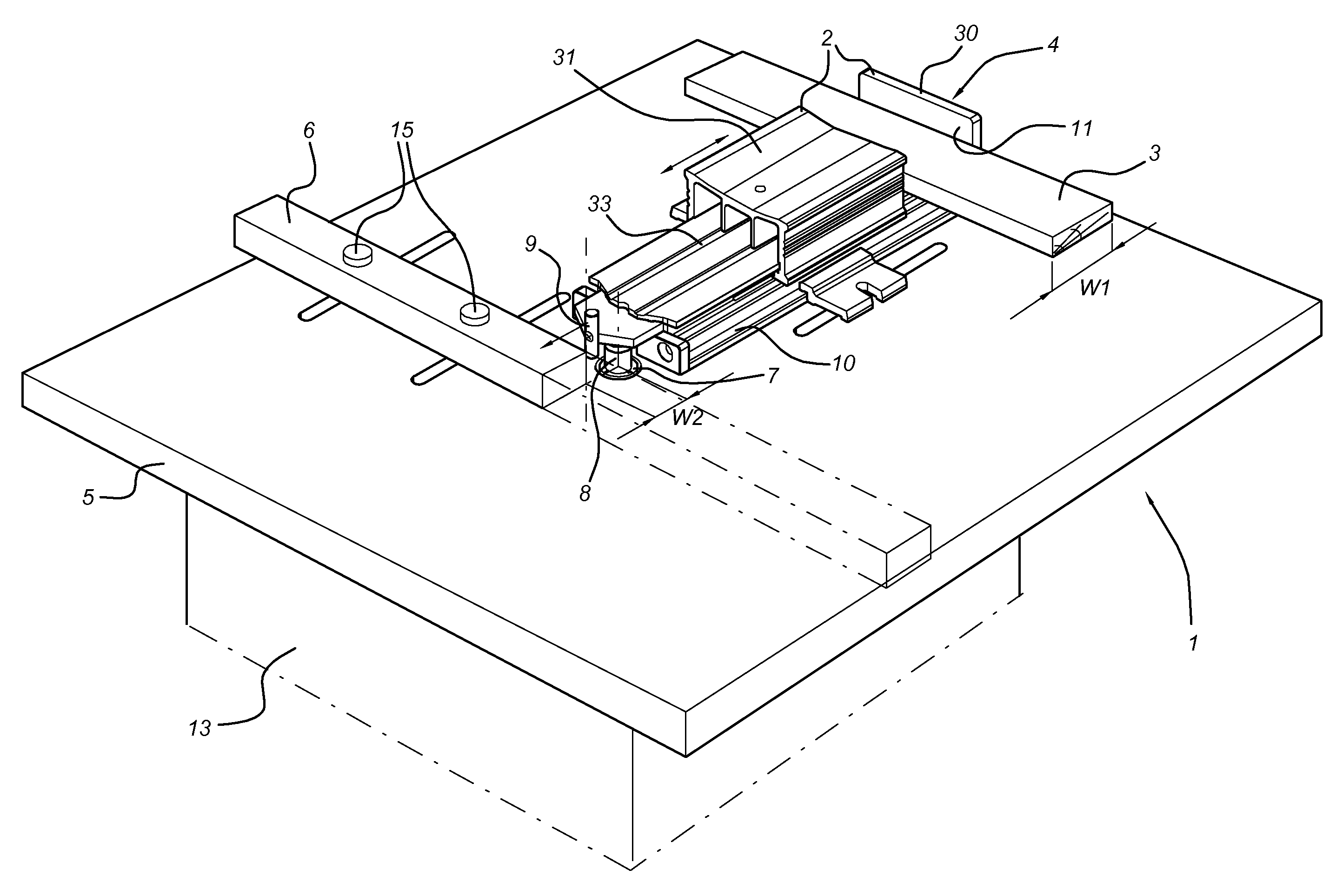
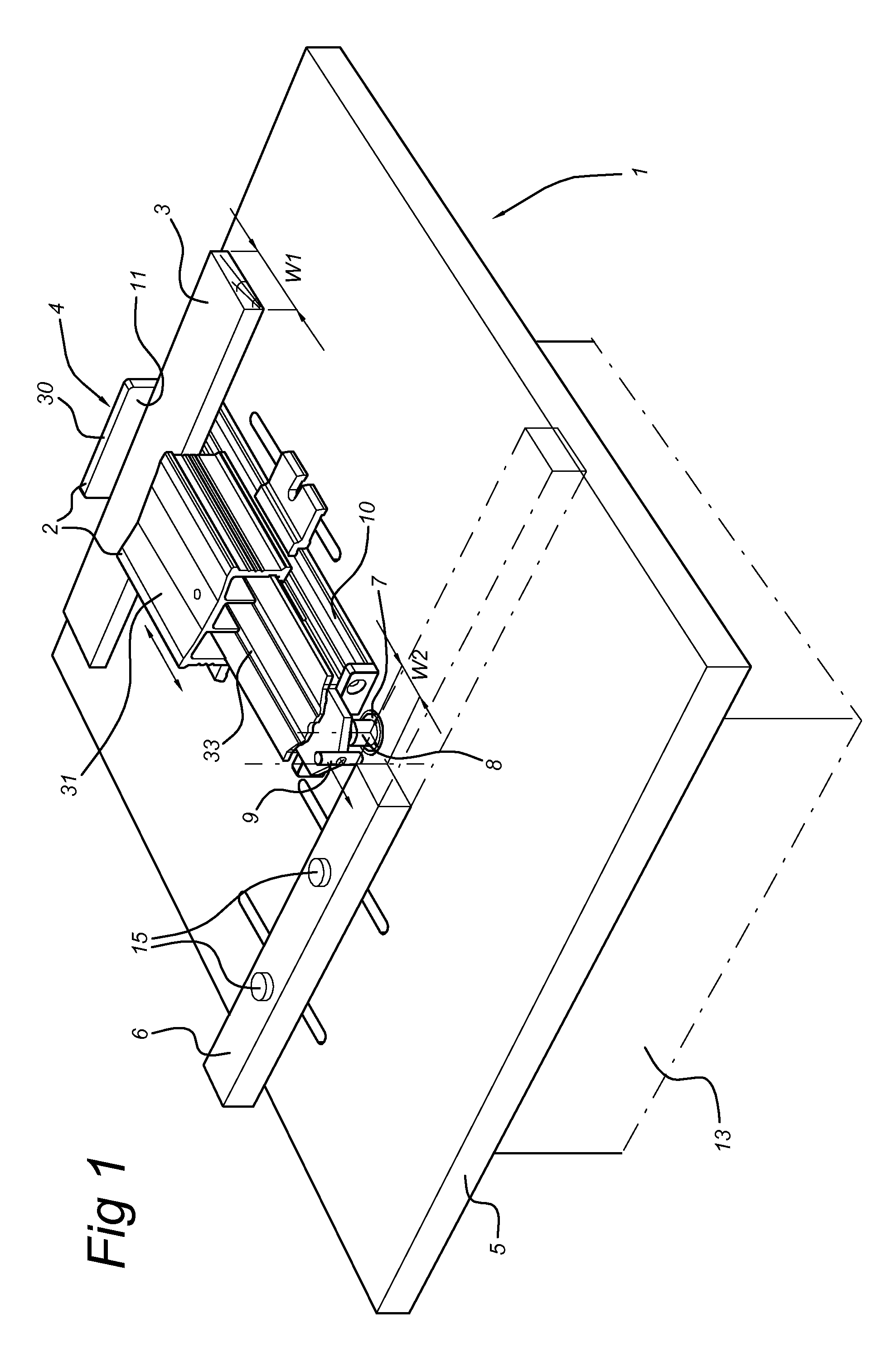
[0050]FIG. 1 shows a router table 1 including a frame 13 and a tabletop 5. The tabletop 5 is used to support a piece of material 3 (for example a piece of wood) to be machined. A plunge or fixed base router for routing out (hollow out) an area in the face of the piece of material 3 is arranged underneath the router table 1. The router includes a base supported by the router table, the base housing a vertically mounted electric motor with a router collet 7 on the end of its motor shaft. The router collet 7 is supported by a frame that is positioned under the router table and is arranged to take up a router bit, which then extends through an opening in the router tabletop 5. The router table further includes a router fence or guiding fence 6 along which the piece of material 3 is...


PUM


Abstract

A system positions a workpiece with respect to a router bit. The system may include a router for routing out a part of the workpiece, a router table for supporting the workpiece, a router fence arranged and constructed to position the workpiece relative to the router during machining, and a positioning device arranged and constructed to position the router fence relative to the router before machining the workpiece, wherein the router comprises a router collet positioned beneath the router table, the router collet being constructed and arranged to engage a router bit extending through an opening in the router table for machining the piece.

Description

BACKGROUND OF THE INVENTION[0001]1. Field of the Invention[0002]The present invention relates to a system and device for positioning a piece to be machined by a router. The invention also relates to the use a system and device for positioning the piece to be machined.[0003]2. Description of the Related Art[0004]A router is a tool, especially used in the woodworking industry, used for milling out (hollow out) an area in the face of a piece of material (workpiece). Usually the material is wood or metal, but applying the router to other types of materials is also possible. There are several types of routers. Nowadays, most common types are spindle type routers (spindle routers), where a router bit is mounted onto a rotatable spindle of an electric motor.[0005]A typical router set-up includes a frame for supporting the router table. The piece of material to be machined is supported by the table. The table has an opening through which a bit protrudes for machining the material. Different...

Claims


Application Information

Patent Timeline
Patent Type & Authority Patents(United States)
IPC IPC(8): B27C5/00B23Q17/00B23Q17/22
CPCB27C5/04
Inventor VAN VALKENBURG, SJOERD ANNE
Owner VAN VALKENBURG SJOERD ANNE
Why Eureka
Try Eureka