Apparatus in spinning preparation for separating foreign objects at conveying equipment for fibre material

a technology of foreign objects and conveying equipment, which is applied in the direction of spray nozzles, lap winding devices, textiles and paper, etc., can solve the problems of large dispersion of blast air jets, large distances between blast nozzles, and large space requirements, and achieve more selective action of blast air currents and reduce the proportion of good fibres

Inactive Publication Date: 2011-08-16
TRUETZSCHLER GMBH & CO KG
View PDF29 Cites 3 Cited by
  • Summary
  • Abstract
  • Description
  • Claims
  • Application Information

AI Technical Summary

Benefits of technology

[0006]It is an aim of the invention to produce an apparatus of the kind described initially that avoids or mitigates the said disadvantages and in particular permits in a structurally simple manner a consistent quality of separation, namely, a reduction in the proportion of good fibres in the waste, and allows a more selective action of the blast air current.
[0011]Because a bar is provided for mounting the blast nozzles, integration of the blast nozzles is facilitated in a simple way. The blast nozzles can be arranged efficiently, for example, closely side by side in the interior of the blast nozzle bar, thus enabling a considerably higher number of blast nozzles across the width of the conveying equipment to be achieved. In addition, the integration permits an especially simple assembly and disassembly of the blast nozzles, e.g. by insertion and removal respectively (exchange). The bar may be of substantially uniform cross-section, and may advantageously include an inner hollow space within which at least a part of each nozzle can be housed. An inner hollow space of the blast nozzle bar is advantageously used simultaneously as a compressed air duct. Another advantage is that the positions of the nozzles relative to one another can be substantially exact owing to mechanical machining in the blast nozzle bar (support profile). The components, for example, blast nozzles and valves, that are integrated in the blast nozzle bar are not susceptible to dirt deposits. Narrow blast nozzles and valves can be used, which further reduces the space requirement. Through the increased number of blast nozzles across the width and their reduced distance from one another, and since the blast nozzles, selectively activated, are directed onto the foreign objects, a strong focus on the foreign objects and removal thereof is possible, so that the undesirable separation of good fibres is substantially reduced.
[0012]The blast nozzle bar is preferably made from an extruded profile, for example, of aluminium, in which the valve inserts are integrated. This therefore enables a plurality of valves, lying side by side close together, to be provided over the width of the conveying equipment and at the same time the storage volume of the blast nozzle bar is increased, for example, doubled. The option of being able to integrate more valves and blast nozzles in the blast nozzle bar substantially reduces the proportion of good fibres in the waste. The apparatus according to the invention provides one or more of the following advantages:

Problems solved by technology

These valves, which are arranged side by side, require a good deal of space.
This results in relatively large distances between the blast nozzles, with a consequent considerable dispersion of the blast air jets.
The blast air is thus effective over relatively wide areas, which leads to an undesirably high separation of good fibres with the foreign objects.
The drawback of this apparatus is the considerable space requirement, which is caused inter alia by the blowing direction of the blast air source (air nozzles) in the area beneath the opening roll.
In addition, it is inconvenient that the blast air source and the valves are located freely in the waste collecting area, which leads to considerable interference to operation, interruptions and the like.
Another disadvantage is that the air nozzles with the magnetic valves are arranged separately across the width of the roll.
A consistent quality of separation and a rapid adjustment when the processed fibre material is changed to one with different proportions of foreign objects is not possible with this apparatus.

Method used


Image

  • Apparatus in spinning preparation for separating foreign objects at conveying equipment for fibre material
  • Apparatus in spinning preparation for separating foreign objects at conveying equipment for fibre material
  • Apparatus in spinning preparation for separating foreign objects at conveying equipment for fibre material

Examples


Embodiment Construction

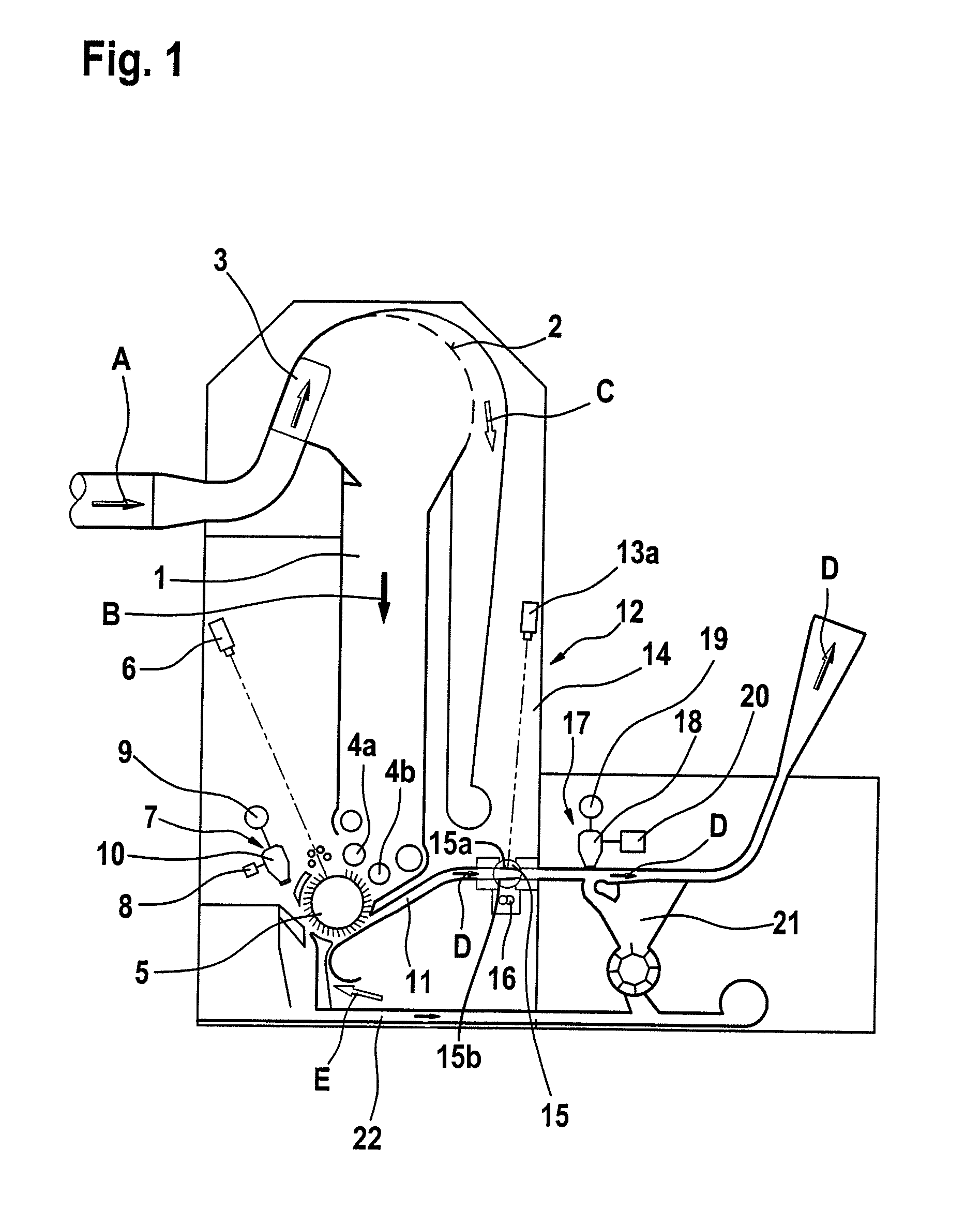
[0047]Referring to FIG. 1, in an apparatus for detecting and separating foreign objects, e.g. the foreign part separator SECUROMAT SP-F2, made by Trützschler GmbH & Co. K.G. of Mönchengladbach, Germany, the upper inlet opening of a feed chute 1 has associated with it an arrangement for the pneumatic supply of a fibre-air flow A, which comprises a fibre material transport fan (not shown), a stationary air-permeable surface 2 for separation (ejection) of the fibre material B from air C with air extraction, and an air flow guide means 3 with movable elements; the fibre material present in the air flow is guided reversibly forwards and backwards transversely over the air-permeable surface 2 and, following impact, the fibre material falls substantially as a result of gravity from the air-permeable surface 2 and enters the feed chute 1 downwards. The slow-speed rolls 4a, 4b have a dual function: they serve as take-off rolls for removing the fibre material B out of the feed chute 1 and at ...


PUM


Abstract

In an apparatus in spinning preparation for separating foreign objects at conveying equipment for fiber material, at least one separation device is associated with the conveying equipment. The separation device comprises an arrangement for producing a blast of air that flows in the direction onto the conveying equipment and generates an air flow that detaches the foreign objects from the conveyed fibers and carries them away. The arrangement comprises a plurality of blast nozzles arranged across the width of the conveying equipment and connected to a compressed air pipe and to valves. To reduce the proportion of good fibers in the waste in a simple manner, and to allow a more selective action of the blast air current, a bar member for mounting the blast nozzles is present and the nozzles are integrated in the bar member.

Description

CROSS REFERENCE TO RELATED APPLICATION[0001]This application claims priority from German Patent Application No. 10 2007 005 049.8 dated Jan. 26, 2007, the entire disclosure of which is incorporated herein by reference.BACKGROUND OF THE INVENTION[0002]The invention relates to an apparatus in spinning preparation for separating foreign objects at conveying equipment for fibre material, for example, cotton, synthetic fibres or the like.[0003]It is known to provide a device for separating the foreign objects associated with the conveying equipment, which device comprises an arrangement for producing a current of blast air that flows in the direction onto the conveying equipment and generates an air stream that detaches the foreign objects from the conveying equipment and carries the foreign objects away, the arrangement comprising a plurality of blast nozzles that are arranged across the width of the conveying equipment and are connected to a compressed air pipe and to valves.[0004]From...

Claims


Application Information

Patent Timeline
Patent Type & Authority Patents(United States)
IPC IPC(8): B05B1/00B07C5/00
CPCD01G23/08D01G31/003
Inventor SCHMITZ, JOERGTEMBURG, KONRAD
Owner TRUETZSCHLER GMBH & CO KG
Why Eureka
Try Eureka