
Lithium ion rechargeable cell

a rechargeable cell and lithium ion technology, applied in the direction of cell components, sustainable manufacturing/processing, final product manufacturing, etc., can solve the problems of inability to make efficient extra space, limited containing capacity, and inability to change and achieve reliably improved power generation efficiency and undetectable change of the capacity of each of the pores

Inactive Publication Date: 2011-08-16
MITSUBISHI MOTORS CORP
View PDF2 Cites 2 Cited by
  • Summary
  • Abstract
  • Description
  • Claims
  • Application Information

AI Technical Summary

Benefits of technology

[0016]The invention has been made to solve the above-mentioned problems. It is an object of the invention to provide a lithium ion rechargeable cell that can be produced to have compact size and high capacity without deterioration in manufacture efficiency.
[0019]It is then possible to reduce the cell case in wall thickness and smoothly pack the electrode group in the cell case without extra space. The cell case is retained in shape so as not to be deteriorated in packageability into the module case, or manufacture efficiency, and power generation efficiency is improved at the same time. In this manner, the lithium ion rechargeable cell can be produced to have compact size and high capacity.
[0021]This prevents the spacer from being deformed so that the capacity of each of the pores is undesirably changed. Consequently the electrode can be constantly well stored in the pores, and the power generation efficiency is reliably improved.

Problems solved by technology

The capacity of the cell case is accordingly limited, too.
If the cell case is fabricated with an undeformable rigid case, it is difficult to make an efficient extra space, and the containing capacity is also limited.
Since the cell case fabricated with a rigid case is limited in capacity, it is difficult to achieve a compact and high-capacity lithium-ion rechargeable cell module.
This causes another problem that voltage is reduced unless electrode plates, an electrolyte and others are changed.
Due to the high adhesion degree, in spite that the lithium ion rechargeable cell needs to use a liquid electrolyte, the electrolyte cannot be sufficiently injected in between the laminated film and the electrode group.
If the electrolyte is not be sufficiently injected into the cell case, this raises problems including an increase in internal resistance, and also incurs a deterioration in power generation efficiency.
If the adhesion degree is lowered, the cell case becomes unstable in shape.
This adversely affects the packageability of the cell case into the module case, that is, the manufacture efficiency of lithium ion rechargeable cells.
Furthermore, if the adhesion degree is simply reduced, gaps between the laminated film and the electrode group would be uneven, and the electrolyte cannot be uniformly injected.
This causes another problem that the power generation efficiency is not successfully improved.

Method used


Image

  • Lithium ion rechargeable cell
  • Lithium ion rechargeable cell
  • Lithium ion rechargeable cell

Examples


Embodiment Construction

[0025]An embodiment of the invention will be described below with reference to the attached drawings.

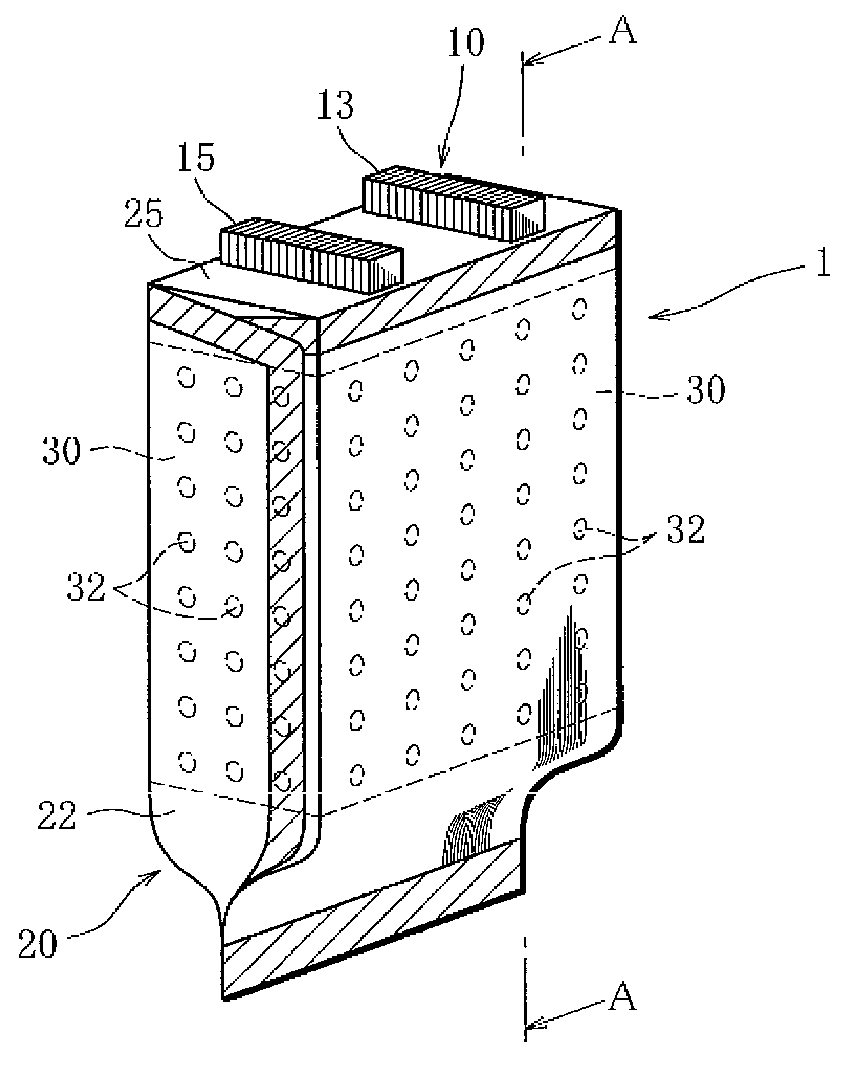
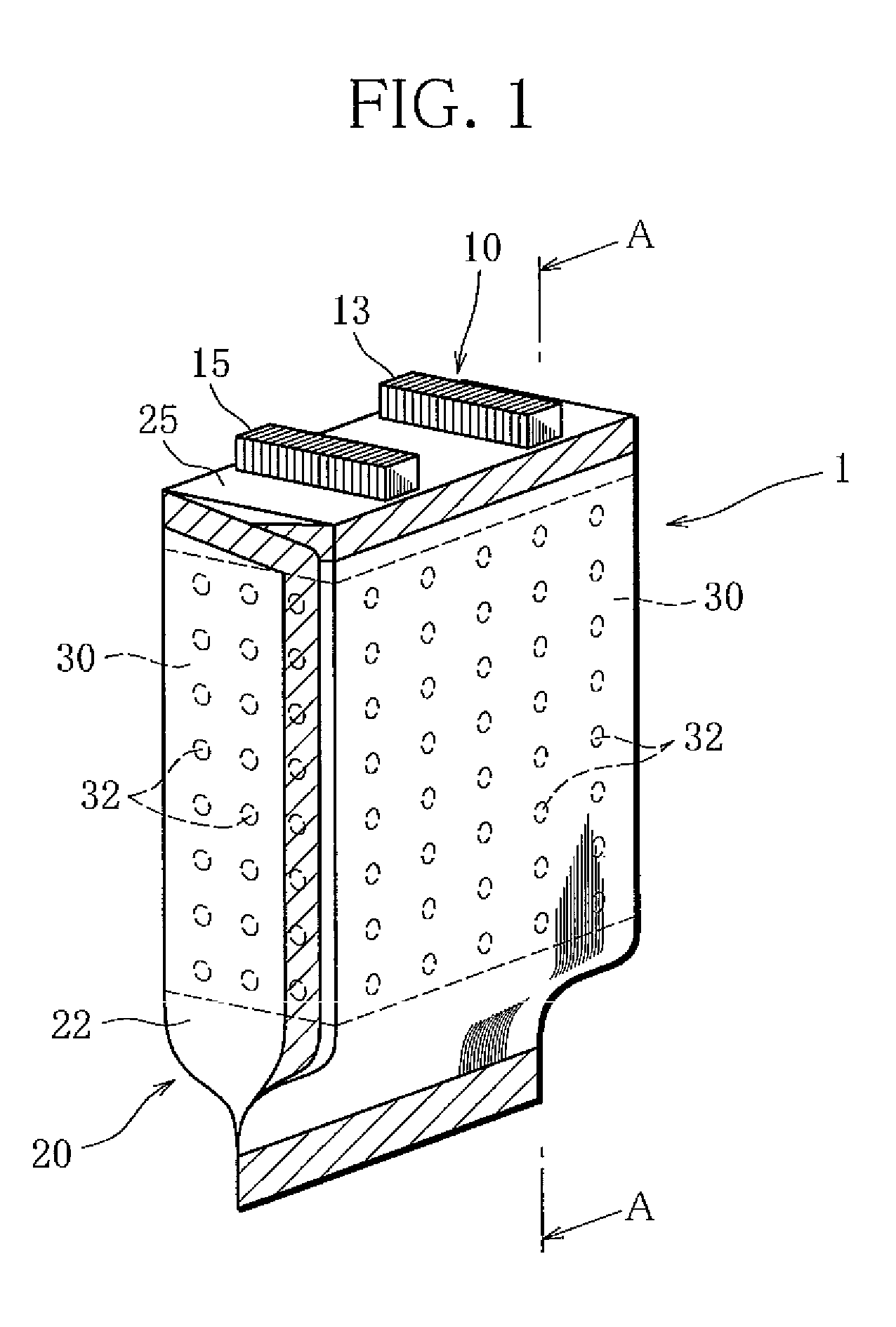
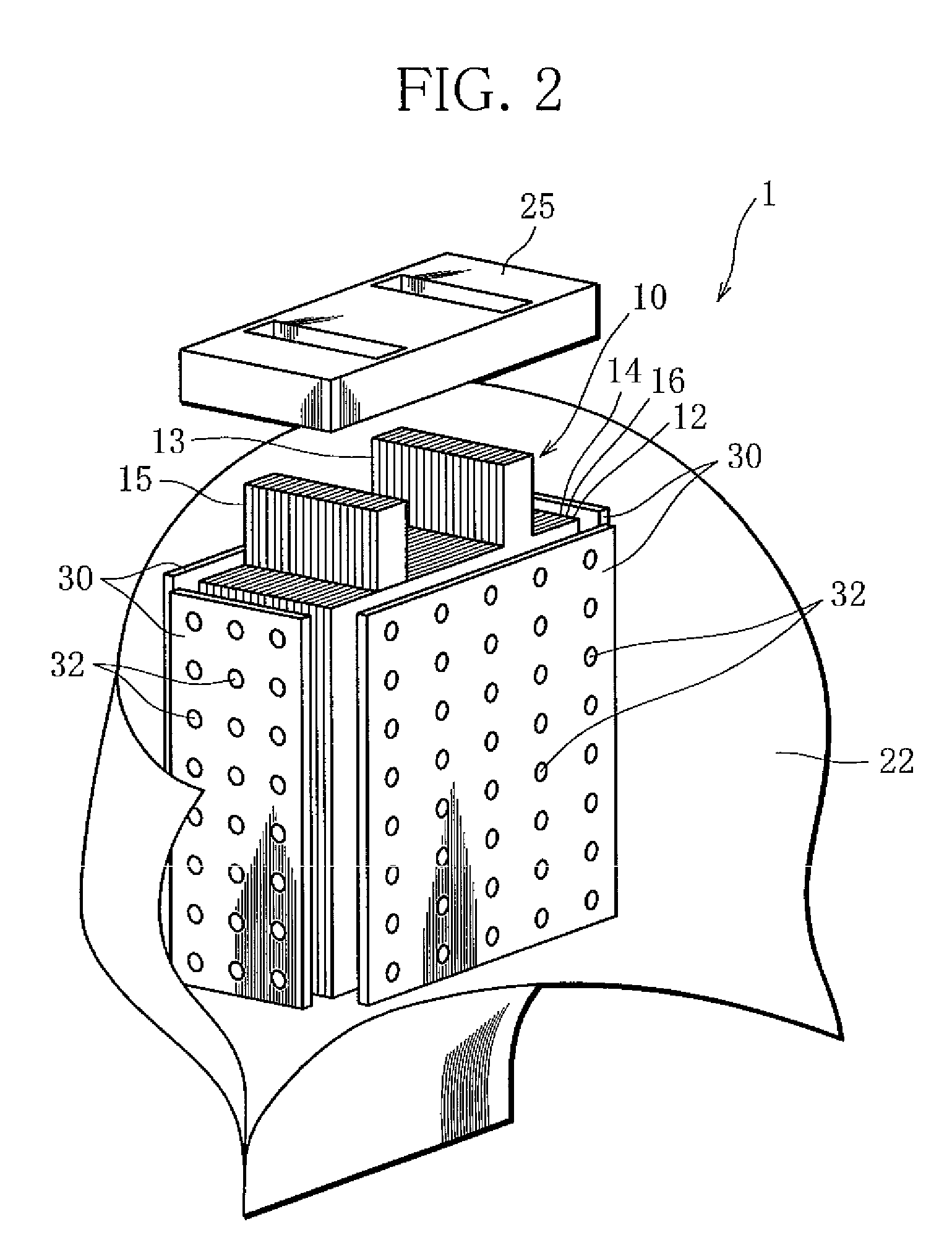
[0026]FIG. 1 is a perspective view of a cell unit 1 of a lithium ion rechargeable cell according to the invention. FIG. 2 is an exploded perspective view of the cell unit 1. FIG. 3 partially shows a cross section, taken along line A-A of FIG. 1.

[0027]The cell unit 1 is one constituent unit of a lithium ion rechargeable cell that is modularized. A plurality of cell units 1 are packed in a module case, not shown, which is fabricated with a rigid case made of resin or metal, to be formed into a lithium ion rechargeable cell.

[0028]The cell unit 1 is basically formed by packing an electrode group 10, in which positive plates 12, negative plates 14, and separator plates 16 are superposed in layers, and an electrolyte into a cell case 20 made of a laminated film 22; depressurizing the electrode group 10 and the laminated film 22 so that the electrode group 10 and the laminated film 22 are f...


PUM

PropertyMeasurementUnit
thicknessaaaaaaaaaa
thicknessaaaaaaaaaa
thicknessaaaaaaaaaa

Abstract

A lithium ion rechargeable cell that is constructed by the steps of forming a cell unit (1) by packing an electrode group (10), in which plate-like positive and negative electrodes (12 and 14) and a plate-like separator (16) are superposed in layers, in a cell case (20) and sealing the electrode group together with an electrolyte; and forming a module by aligning and packing a plurality of cell units in a module case. The cell case is made of a laminated film (22). A porous spacer (30) made of insulating material is interposed in between the entire circumferential surface or partial surface of the electrode group and the laminated film.

Description

BACKGROUND OF THE INVENTION[0001]1. Field of the Invention[0002]The present invention relates to a lithium ion rechargeable cell, and more specifically, to a cell case of a lithium ion rechargeable cell.[0003]2. Description of the Related Art[0004]In general, a lithium ion rechargeable cell is modularized. One module is constructed in the following manner. First, an electrode group, in which plate-like positive and negative electrodes and a plate-like separator are alternately superposed in layers, is packed in a cell case and sealed together with an electrolyte. The result is a cell unit. Several cell units are aligned and packed in a module case to produce a module.[0005]A cell case and a module case have been generally fabricated with an undeformable rigid case that is made of, for example, resin or metal.[0006]Therefore the capacity of the module case made with a rigid case is previously determined, so that the total cubic volume of the cell units contained in the module case is...

Claims


Application Information

Patent Timeline
Patent Type & Authority Patents(United States)
IPC IPC(8): H01M2/08H01M10/05H01M10/0525H01M10/0585H01M50/105H01M50/474H01M50/486H01M50/489H01M50/491
CPCH01M2/0202H01M2/14H01M10/052H01M10/0585Y02E60/122Y02E60/10Y02P70/50H01M50/486H01M50/105H01M50/491H01M50/489H01M50/474
Inventor TOMINAGA, YUKIMIYASHITA, TAKAYA
Owner MITSUBISHI MOTORS CORP
Learn More