
Duty cycle correction circuitry

a circuit and duty cycle technology, applied in pulse manipulation, pulse duration/width modulation, pulse technique, etc., can solve the problems of inability to achieve, insufficient method, and significant slowing of system clock

Active Publication Date: 2011-08-16
ALTERA CORP
View PDF8 Cites 3 Cited by
  • Summary
  • Abstract
  • Description
  • Claims
  • Application Information

AI Technical Summary

Benefits of technology

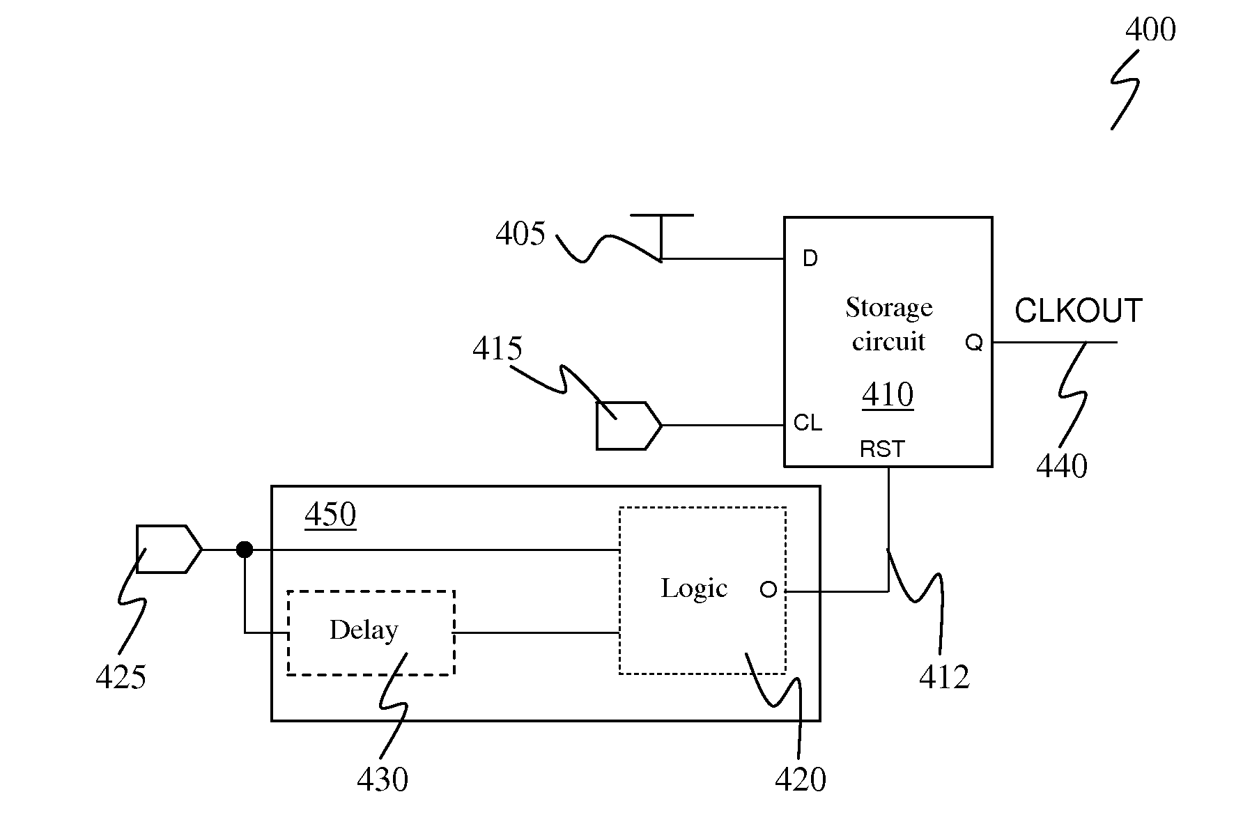
In yet another embodiment in accordance with the present invention, a duty cycle correction circuit is provided. The circuit includes a flip flop. The flip flop has a data input terminal that receives a logic high signal, a clock input terminal that receives a clock input signal, and a reset terminal that receives a reset signal. A reset circuit generates the reset signal to reset the flip flop based on the phase shifted version of the clock input signal. The flip flop modifies the clock input signal according to the reset signal to generate a clock output signal having substantially even duty cycle. In one embodiment, the waveform of the clock output signal is a substantially symmetrical waveform derived from the clock input signal, which has an uneven duty cycle

Problems solved by technology

However, in high speed designs where the output clocks are already running at a high frequency, e.g., 5 GHz and above, such a method is not feasible because it is very difficult, or even impossible, to double an already high frequency clock.
Furthermore, by dividing the clock rate, this method would slow down the system clock considerably.
However, this method is inadequate because it has a limited correction range and the inverters used invariably increase the power consumption of the circuit.

Method used


Image

  • Duty cycle correction circuitry
  • Duty cycle correction circuitry
  • Duty cycle correction circuitry

Examples


Embodiment Construction

The following embodiments describe circuits and a method for tuning an integrated circuit (IC).

It will be obvious, however, to one skilled in the art, that the present invention may be practiced without some or all of these specific details. In other instances, well-known operations have not been described in detail in order not to unnecessarily obscure the present invention.

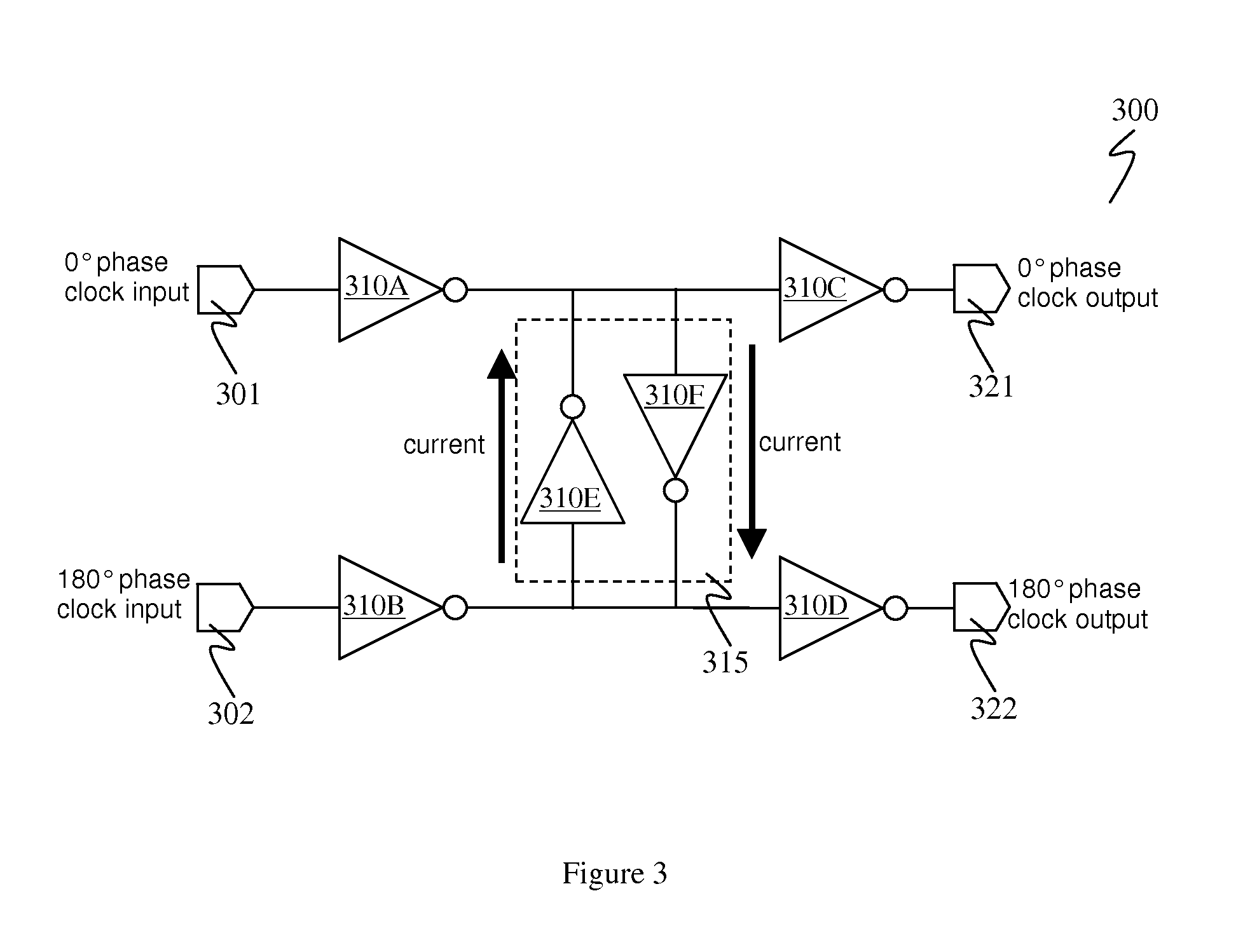
The embodiments described herein provide techniques to create an IC with a clock duty cycle correction circuit that outputs a clock with approximately 50% duty cycle across all PVT ranges. It should be appreciated that in high speed quadrature system, i.e., a system running above 1 GHz, the voltage-controlled oscillator (VCO) output clocks may not have a 50%, or close to 50%, duty cycle. As one skilled in the art should know, quadrature clocks are widely used in many applications such as phase interpolators, CDR circuits and VCOs. A 50% duty cycle is important for high frequency devices or high-speed application...


PUM


Abstract

Circuits and a method for tuning an integrated circuit (IC) are disclosed. The IC includes a storage circuit coupled to receive a data signal, a clock input signal and a reset signal. The storage circuit may be used to generate a clock signal. The reset signal is supplied by a reset circuit. The reset circuit may include one or more logic gates to generate the reset signal. The reset circuit receives a phase shifted version of the clock input signal and the reset signal is generated based on the phase shifted version of the clock input signal. In one embodiment, the reset signal is a series of pulses generated at specific intervals to shift the output of the storage circuit from logic high level to logic low level.

Description

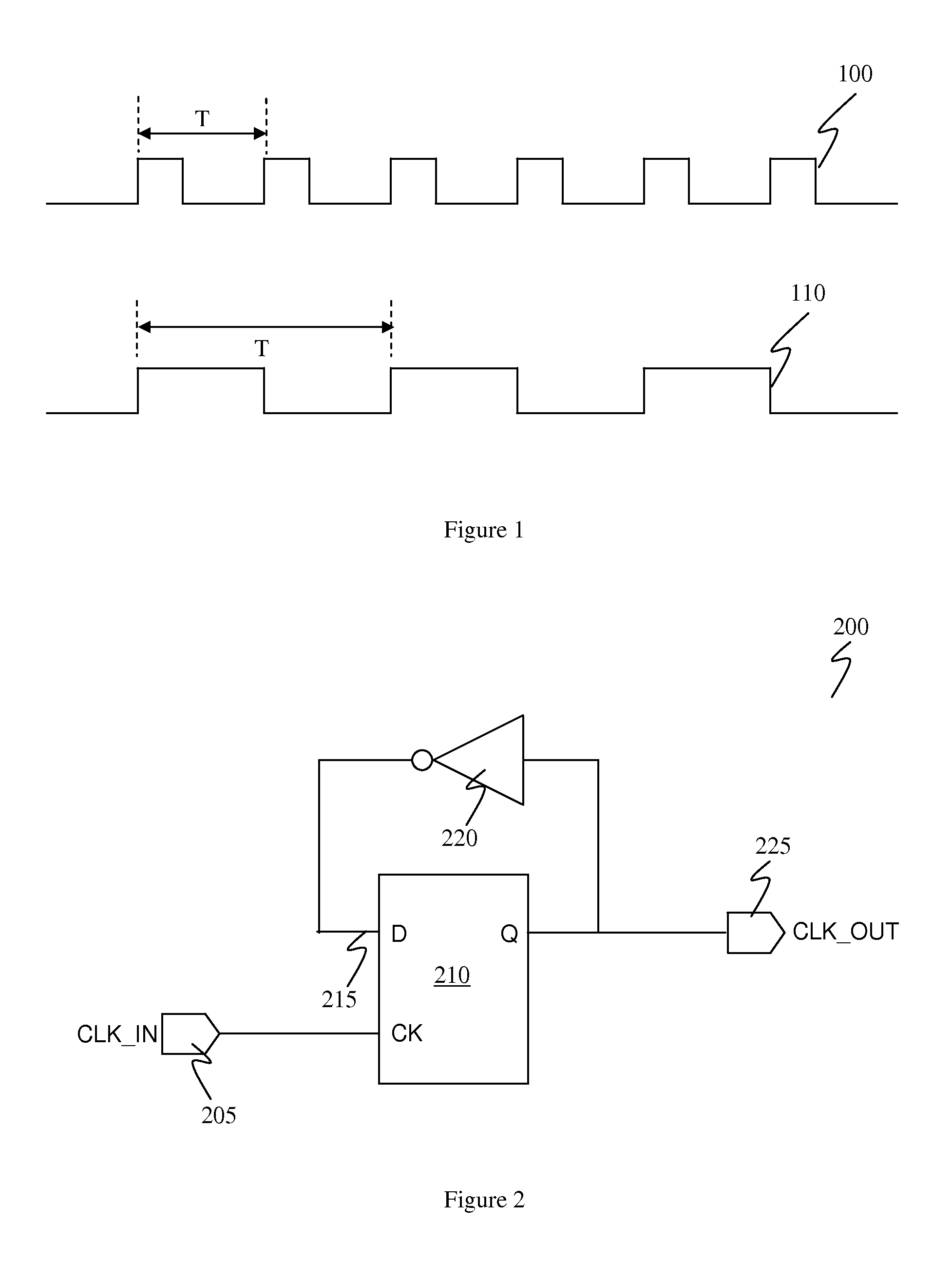
BACKGROUNDQuadrature clocks are widely used in many applications such as a phase interpolator and a half-rate clock data recovery (CDR) circuit. The generated quadrature clocks are required to be in symmetrical or equally divided phases. In other words, each clock period needs to have equal high and low periods, or an approximately 50% duty cycle. In a rectangular waveform, a 50% duty cycle can be described as the percentage of the full cycle that the signal remains at logic 1. For instance, if the signal spends half the clock period at logic 1 and the other half at logic 0, then the waveform generated would be a waveform with a 50% duty cycle.Usually, the 50% duty cycle is achieved by doubling the clock rate or increasing the frequency of the clock rate before dividing the clock rate by 2. However, in high speed designs where the output clocks are already running at a high frequency, e.g., 5 GHz and above, such a method is not feasible because it is very difficult, or even impossib...

Claims


Application Information

Patent Timeline
Patent Type & Authority Patents(United States)
IPC IPC(8): H03K3/017
CPCH03K5/1565
Inventor PAN, MINGDESHIH, SHOU-POLUO, MEIDING, WEIQI
Owner ALTERA CORP
Learn More