

Imaging optical lens assembly
- Summary
- Abstract
- Description
- Claims
- Application Information
AI Technical Summary
Benefits of technology
Problems solved by technology
Method used
Image

Examples
first embodiment
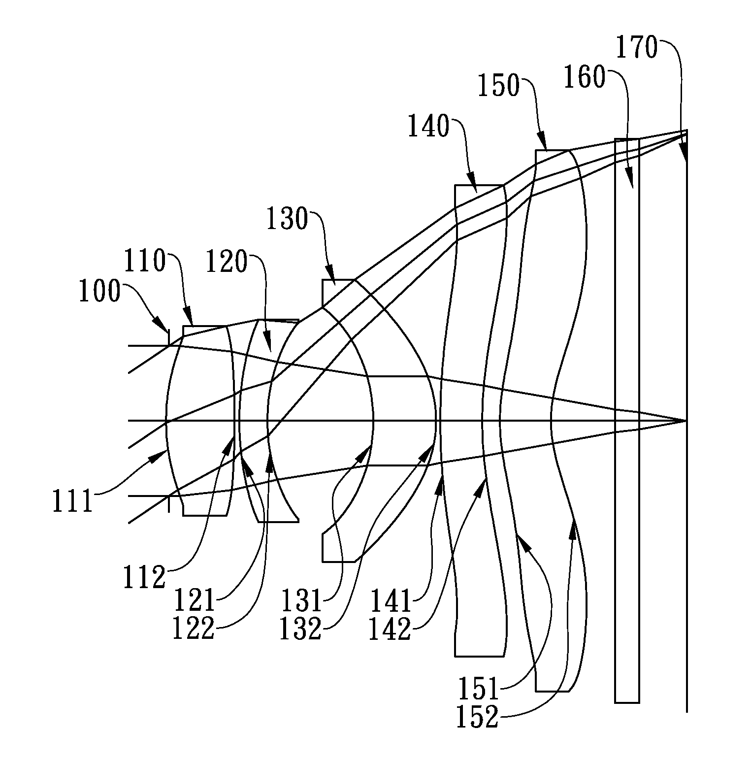
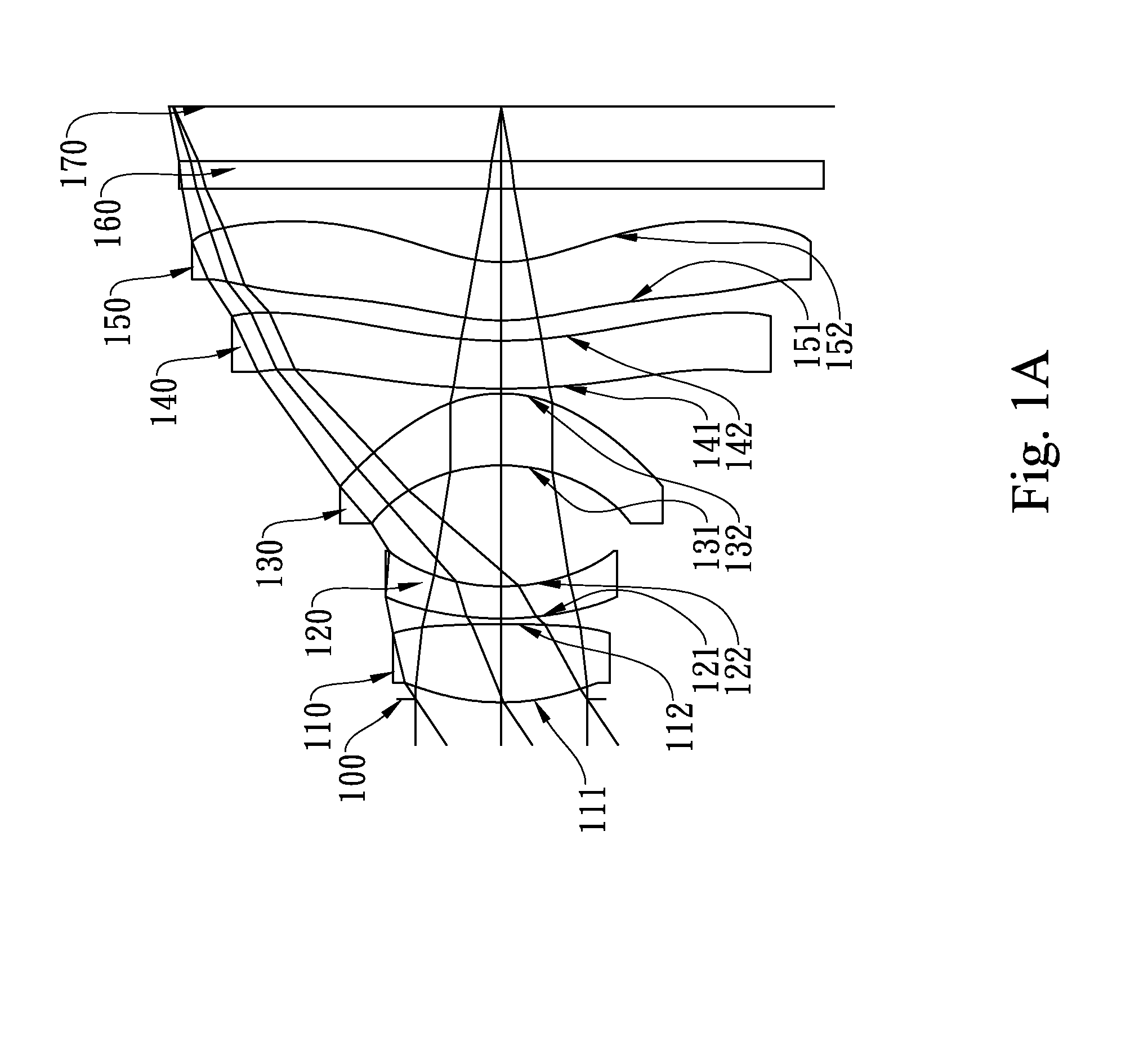
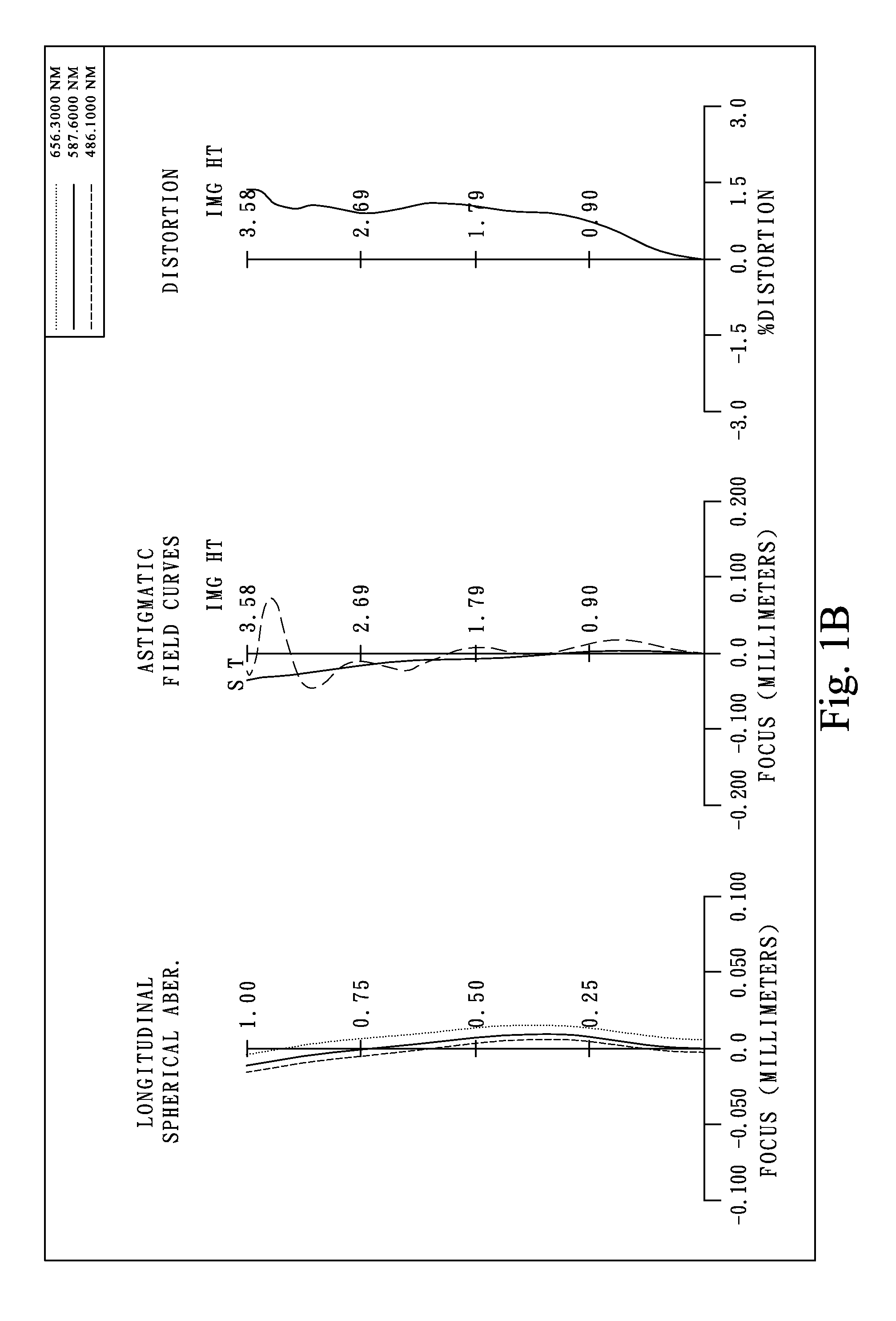
[0069]In the present imaging optical lens assembly, the focal length of the imaging optical lens assembly is f, and it satisfies the relation: f=5.27 (mm).
[0070]In the first embodiment of the present imaging optical lens assembly, the f-number of the imaging optical lens assembly is Fno, and it satisfies the relation: Fno=2.80.
[0071]In the first embodiment of the present imaging optical lens assembly, half of the maximal field of view of the imaging optical lens assembly is HFOV, and it satisfies the relation: HFOV=34.0 deg.
[0072]In the first embodiment of the present imaging optical lens assembly, the Abbe number of the first lens element 110 is V1, the Abbe number of the second lens element 120 is V2, and they satisfy the relation:
V1−V2=48.8.
[0073]In the first embodiment of the present imaging optical lens assembly, the radius of curvature on the object-side surface 111 of the first lens element 110 is R1, the focal length of the imaging optical lens assembly is f, and they satisf...
second embodiment
[0086]In the present imaging optical lens assembly, the focal length of the imaging optical lens assembly is f, and it satisfies the relation: f=5.27 (mm).
[0087]In the second embodiment of the present imaging optical lens assembly, the f-number of the imaging optical lens assembly is Fno, and it satisfies the relation: Fno=2.40.
[0088]In the second embodiment of the present imaging optical lens assembly, half of the maximal field of view of the imaging optical lens assembly is HFOV, and it satisfies the relation: HFOV=34.0 deg.
[0089]In the second embodiment of the present imaging optical lens assembly, the Abbe number of the first lens element 210 is V1, the Abbe number of the second lens element 220 is V2, and they satisfy the relation:
V1−V2=34.5.
[0090]In the second embodiment of the present imaging optical lens assembly, the radius of curvature on the object-side surface 211 of the first lens element 210 is R1, the focal length of the imaging optical lens assembly is f, and they sa...
third embodiment
[0103]In the present imaging optical lens assembly, the focal length of the imaging optical lens assembly is f, and it satisfies the relation: f=5.44 (mm).
[0104]In the third embodiment of the present imaging optical lens assembly, the f-number of the imaging optical lens assembly is Fno, and it satisfies the relation: Fno=2.75.
[0105]In the third embodiment of the present imaging optical lens assembly, half of the maximal field of view of the imaging optical lens assembly is HFOV, and it satisfies the relation: HFOV=33.2 deg.
[0106]In the third embodiment of the present imaging optical lens assembly, the Abbe number of the first lens element 310 is V1, the Abbe number of the second lens element 320 is V2, and they satisfy the relation:
V1−V2=32.5.
[0107]In the third embodiment of the present imaging optical lens assembly, the radius of curvature on the object-side surface 311 of the first lens element 310 is R1, the focal length of the imaging optical lens assembly is f, and they satisf...
PUM
 Abstract
Description
Claims
Application Information