Network routing with path identifiers

a network routing and path identification technology, applied in the field of packet routing, can solve the problems of frequent runtime problems, lossy links, and limited resources of networks, and achieve the effect of facilitating the computation of routing paths

Active Publication Date: 2011-08-16
CISCO TECH INC
View PDF7 Cites 206 Cited by
  • Summary
  • Abstract
  • Description
  • Claims
  • Application Information

AI Technical Summary

Benefits of technology

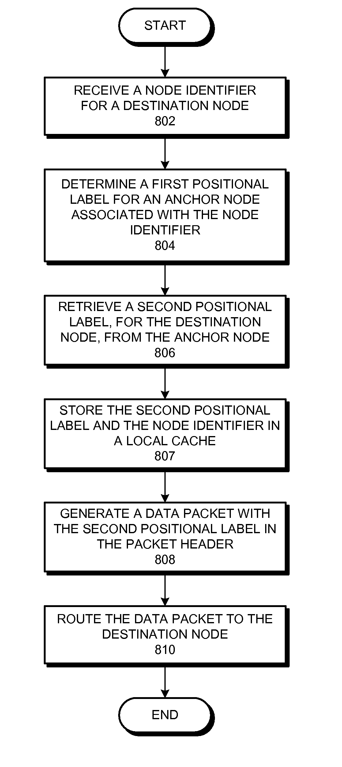
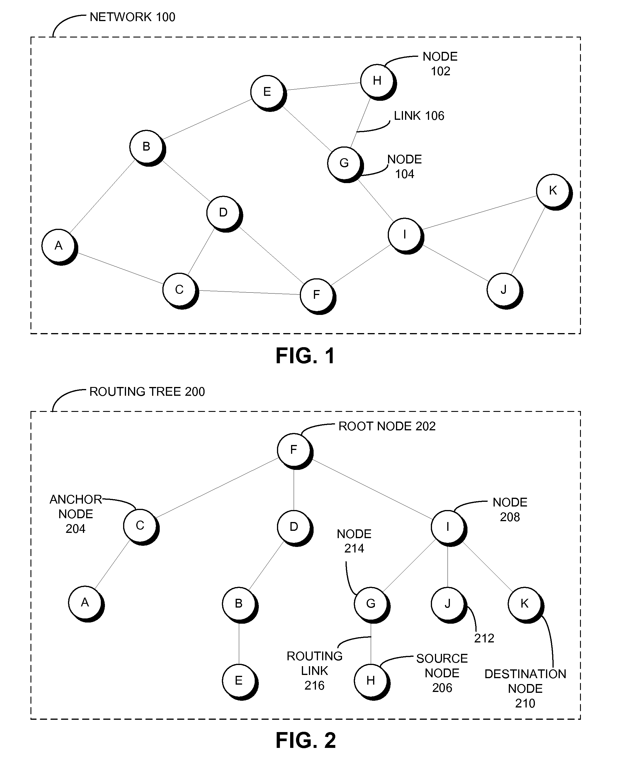
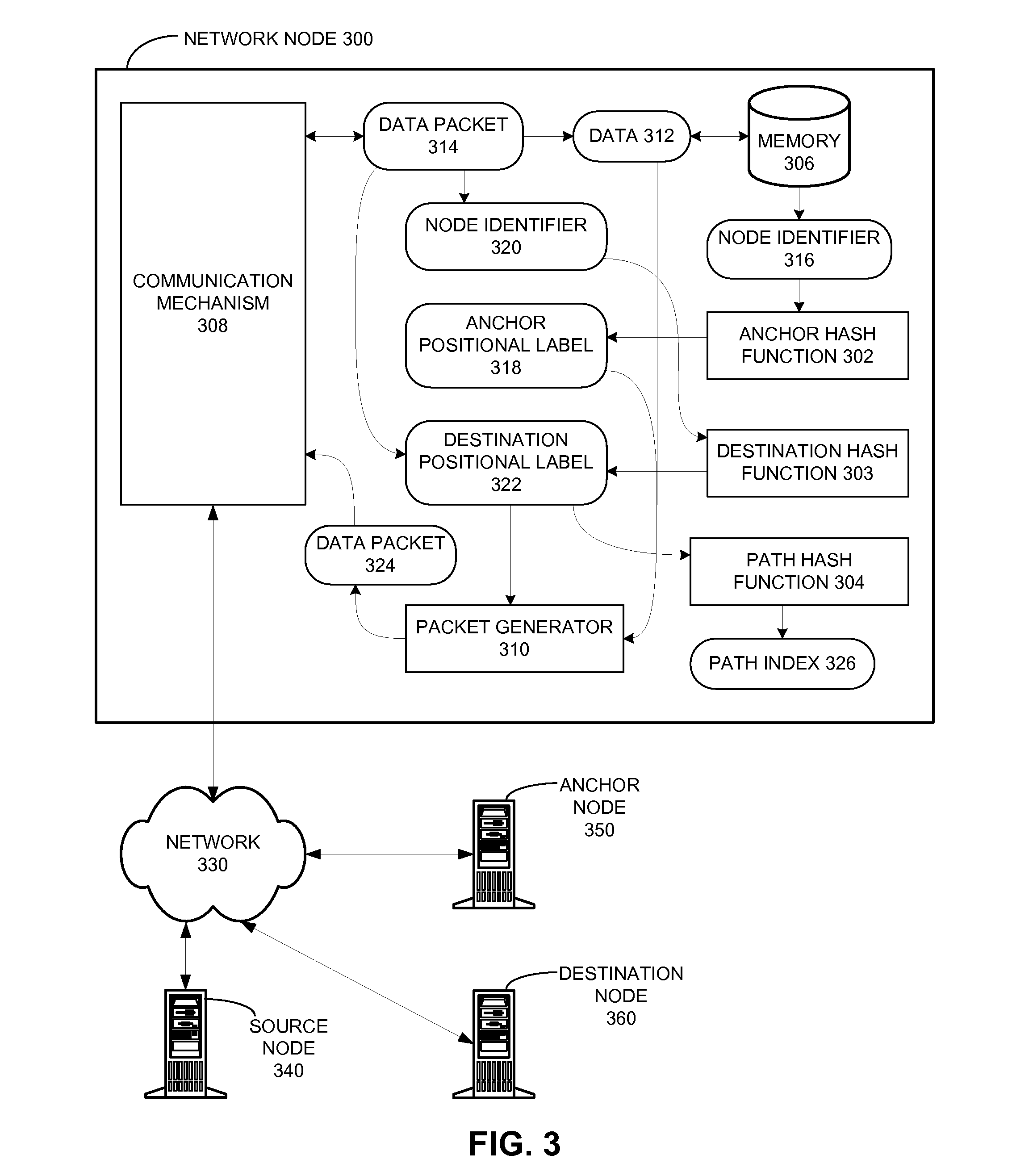
[0010]In a variation on this embodiment, a positional label facilitates computing a routing path from the root node to a corresponding destination node. The positional label comprises a path identifier and a path distance value. The path identifier of the positional label is used by a respective node on the routing path to determine a corresponding child node that is on the routing path. Furthermore, the path distance value of the positional label specifies a distance along the routing path to reach the destination node from the root node.

Problems solved by technology

Unfortunately, MANETs frequently experience runtime issues associated with lossy links, constrained resources, and other complications due to node mobility.
These runtime issues can create a challenge for successfully deploying MANETs capable of achieving a dependable performance level.
As with any network protocol, routing in MANETs is subject to various types of overhead, which can influence how a communication protocol is designed and implemented for a given MANET.
This technique is viable for small networks that do not form long acyclic paths, but suffers from overhead issues with networks that have a large node density and / or diameter.
Second, as the network increases in size, the length of the header path will also increase.
These two overhead issues can require a packet to increase in size, or require more packets for communicating a given amount of data, as the number of computing nodes in a computer network increases.
This technique is viable for small networks, but also suffers from overhead issues for large networks.
First, large networks require large decision tables at each node.
Second, large networks cause the nodes to experience a large signaling overhead for maintaining the network state information at each node.
These two overhead issues can cause a memory overhead, or cause performance degradation at a respective node, as a network increases in size.

Method used


Image

  • Network routing with path identifiers
  • Network routing with path identifiers
  • Network routing with path identifiers

Examples


Embodiment Construction

[0030]The following description is presented to enable any person skilled in the art to make and use the invention, and is provided in the context of a particular application and its requirements. Various modifications to the disclosed embodiments will be readily apparent to those skilled in the art, and the general principles defined herein may be applied to other embodiments and applications without departing from the spirit and scope of the present invention. Thus, the present invention is not limited to the embodiments shown, but is to be accorded the widest scope consistent with the principles and features disclosed herein.

[0031]The data structures and code described in this detailed description are typically stored on a computer-readable storage medium, which may be any device or medium that can store code and / or data for use by a computer system. The computer-readable storage medium includes, but is not limited to, volatile memory, non-volatile memory, magnetic and optical st...


PUM


Abstract

One embodiment of the present invention provides a system that communicates a data packet in a network to a target node. In doing so, the system receives a node identifier for the target node, and determines a first positional label, based in part on the node identifier, for reaching a first anchor node from a root node in the network. The first anchor node stores a second positional label for reaching the target node from the root node in the network, which comprises a number of nodes coupled to the root node in a tree topology. The system then retrieves the second positional label from the first anchor node, and communicates the data packet to the target node based in part on the second positional label.

Description

STATEMENT REGARDING FEDERALLY SPONSORED RESEARCH OR DEVELOPMENT[0001]This invention was made with government support under FA8750-07-C-0169 awarded by DARPA. The government has certain rights in the invention.BACKGROUND[0002]1. Field[0003]The present disclosure generally relates to packet routing within a computer network. More specifically, the present disclosure relates to techniques and systems for implementing an optimal routing protocol using fixed-length positional labels.[0004]2. Related Art[0005]Mobile Ad hoc NETworks (MANETs) are becoming increasingly popular as mobile computing becomes an integral part of the modern lifestyle. Furthermore, there are an increasing number of scientific applications for wireless sensor nodes, which employ MANETs as their communication framework. Unfortunately, MANETs frequently experience runtime issues associated with lossy links, constrained resources, and other complications due to node mobility. These runtime issues can create a challenge...

Claims


Application Information

Patent Timeline
Patent Type & Authority Patents(United States)
IPC IPC(8): H04L12/28
CPCH04L45/04H04L45/54
Inventor SOLIS, IGNACIOGARCIA-LUNA-ACEVES, JOSE J.BRAYNARD SILBERSTEIN, REBECCA L.
Owner CISCO TECH INC
Why Eureka
Try Eureka