Internal combustion engine

Active Publication Date: 2011-08-23
SAVVAKIS SAVVAS
View PDF24 Cites 3 Cited by
  • Summary
  • Abstract
  • Description
  • Claims
  • Application Information

AI Technical Summary

Benefits of technology

[0004]what is important to an engine is the output torque of its engine-shaft, (crankshaft in the case of a reciprocative motor). In order to maximize this torque, it is necessary to maximize the torque that is produced on the engine-shaft because of the exhaust gas' expansion as well as to minimize the resistant torque produced by the air or air-fuel mixture compression. Generally, the torque is defined as the product of the applied 
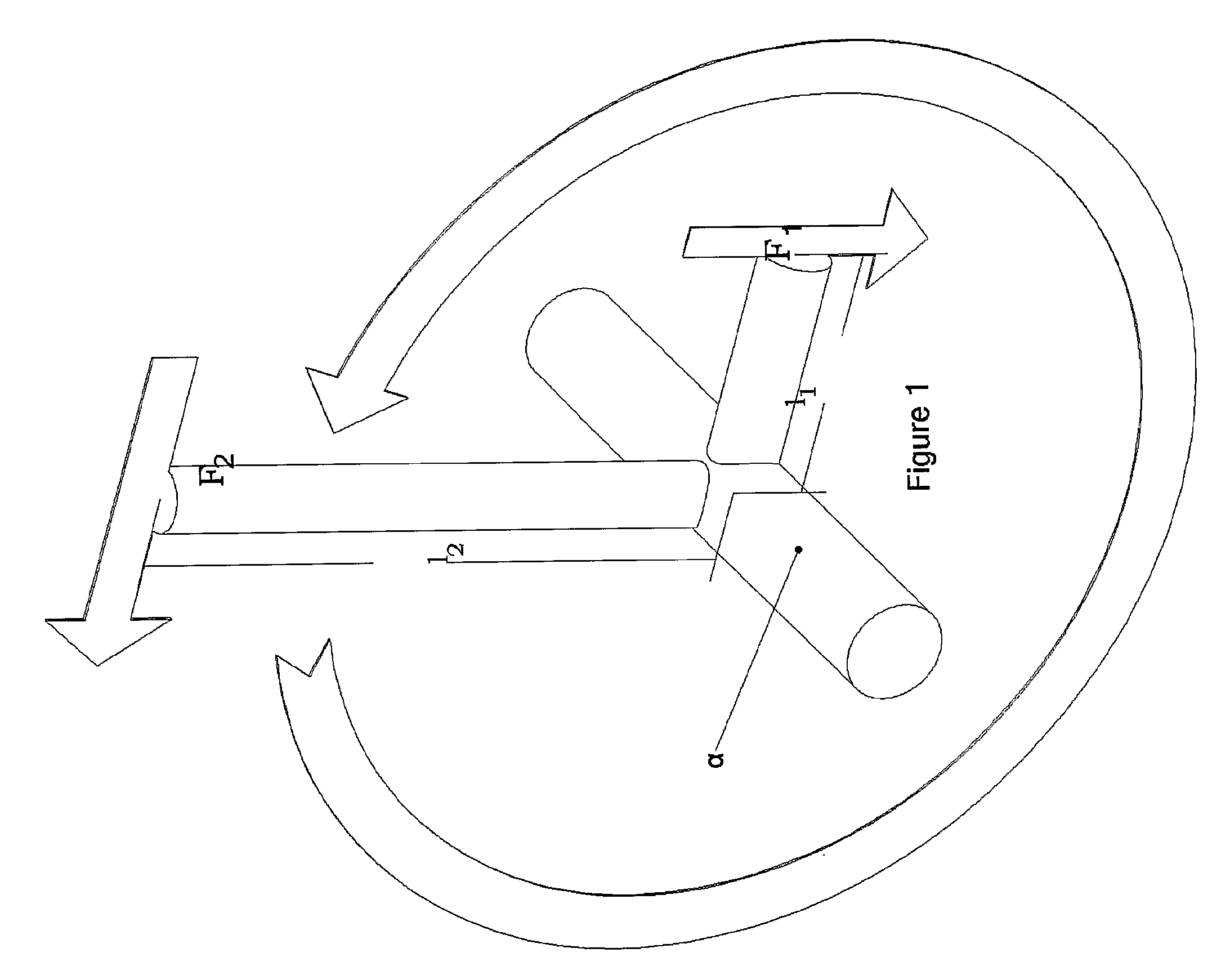
force vector times the vector from the axis of rotation to the point on which the force is acting. Thus, it is easy to imagine an axis (α) on which two arms are located, with lengths L1 and L2 for the compression and expansion process, respectively (FIG. 1). If the forces of compression and expansion, F1 and F2, are applied respectively on the edge of the two arms, L1 and L2, in order to minimize the torque that produced on the compression-arm L1, it is necessary to minimize or even zero the length of the compression-arm. On the contrary, in order to maximize the expansion-torque produced by the force F2 on the expansion-arm, it is necessary to have an expansion-arm L2 as long as possible. In the case of compression, this can be easily succeeded by locating the compression-chamber and its 
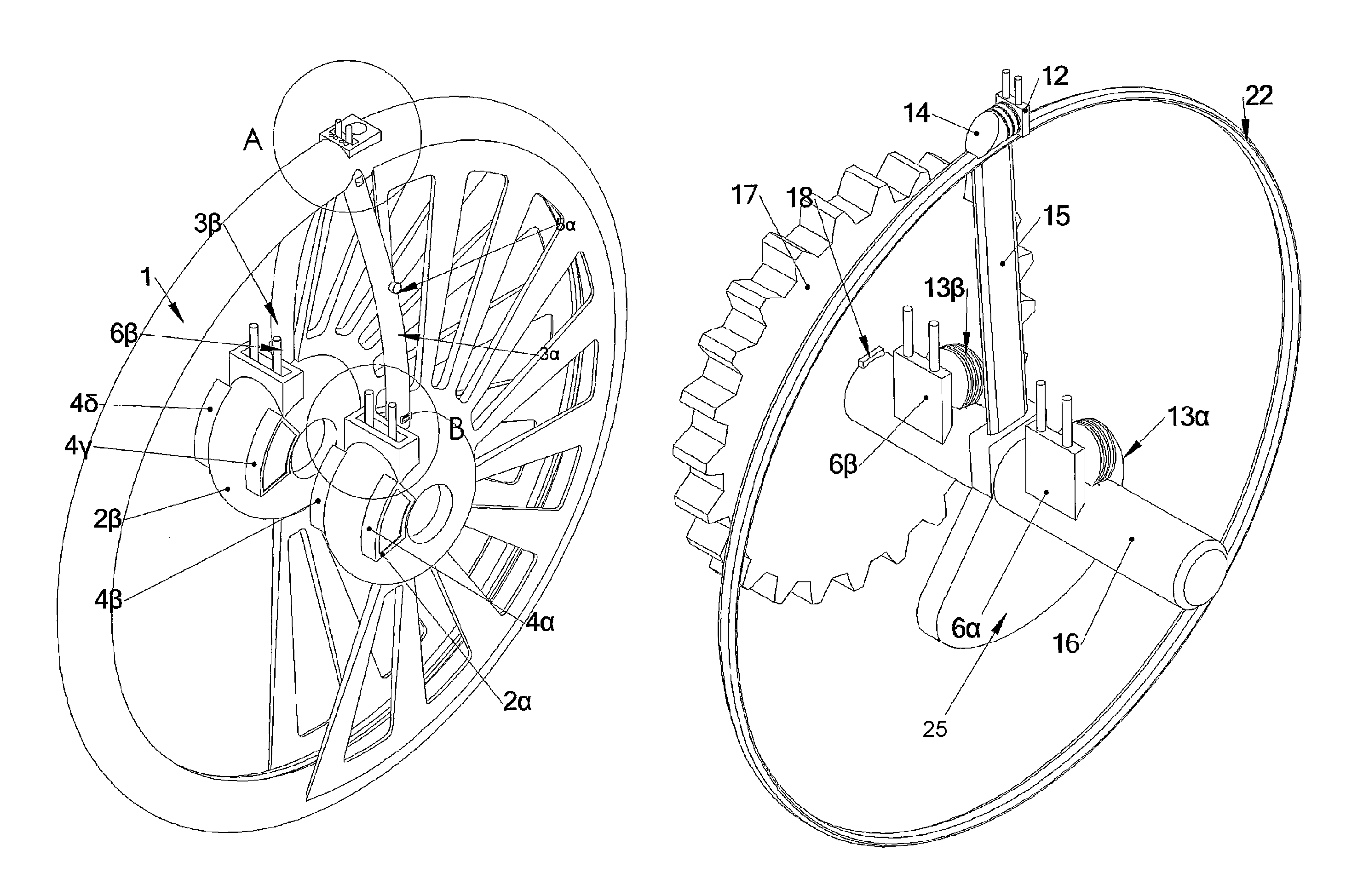
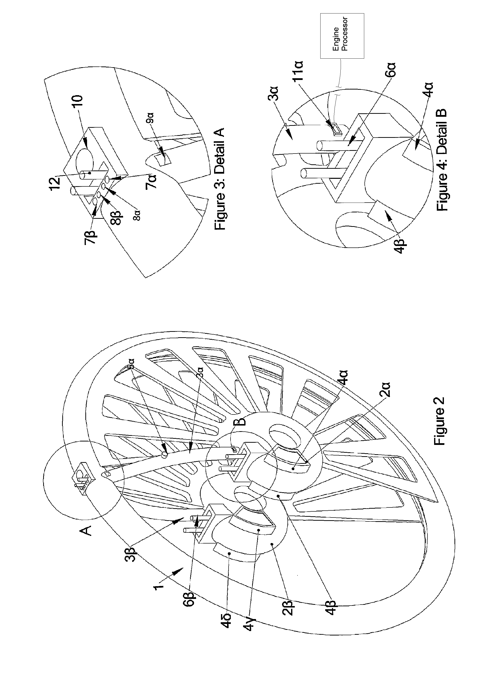
piston (compression piston) on the cylindrical surface of the engine-shaft.

Problems solved by technology

In the case of using a single transfer canal and compressing the air or air-fuel mixture in a pressure much higher than the desired in order for the fluid to reach the combustion chamber with a pressure close to the desired, in spite of its expansion inside the canal, the canal's volume is so big, in comparison to the volume

Method used


Image

  • Internal combustion engine
  • Internal combustion engine
  • Internal combustion engine

Examples


Embodiment Construction

[0033]The motor consists of four moving and one stable part which are depicted in the FIGS. 2 to 6:[0034]The stationary external block of the engine (FIG. 2) comprising of the combustion-expansion chamber (1), the induction-compression chambers (2α and 2β), the pressure chambers (3α and 3β) and the air filters (4α, 4β, 4γ and 4δ). The air filters are located on the shells of the compression chambers in the inlet openings of the atmospheric air. In the figures, the air-filters are located on both sides of every compression chamber creating two inlets of atmospheric air in every chamber. The pressure chambers may have every possible shape. However, in the figures a canal-shape is chosen so that the chamber will have the minimum possible volume. On the shell (1) two fuel injectors (7α and 7β) and two spark-plugs (8α and 8β) are fitted. The numbers 6 and 12 represent the sliding ports of compression- and expansion-chamber, respectively. The place (10) is the point where the exhaust gase...


PUM


Abstract

An engine with expansion piston located on the end of a motion arm connected to the engine shaft. On the shaft, rotating compression pistons are mounted. The distance between the two piston types allows for the production of great torque. The geometry of expansion chamber and compression chamber is concentric toroidal. A pressure chamber stores the air-fuel mixture coming from the compression chamber to the expansion chamber and is therefore interposed between the two. The timing of the two or more sliding ports attached to the compression chambers determines the compression volume, while the valves control the communication of the pressure chamber with the other chambers.

Description

CROSS-REFERENCE TO RELATED APPLICATIONS[0001]This application is an U.S. national phase application under 35 U.S.C. §371 based upon co-pending International Application No. PCT / GR2006 / 000027 filed on Jun. 2, 2006. Additionally, this U.S. national phase application claims the benefit of priority of co-pending International Application No. PCT / GR2006 / 000027 filed on Jun. 2, 2006 and Greece Application No. 20050100405 filed on Aug. 1, 2005. The entire disclosures of the prior applications are incorporated herein by reference. The international application was published on Feb. 8, 2007 under Publication No. WO 2007 / 015114.BACKGROUND OF THE INVENTIONField of the Invention[0002]The current invention request describes the function of a rotary motor which may replace the existent internal combustion engines in most of their today applications.SUMMARY OF THE INVENTION[0003]This engine has the following special structural characteristics:[0004]what is important to an engine is the output torq...

Claims


Application Information

Patent Timeline
IPC IPC(8): F02B53/00F01C1/34F02B53/08F01C1/00F04C2/00F04C18/00
CPCF01C1/356F01C11/004F03C2/304F01C1/00F02B53/08F02B55/00
Inventor SAVVAKIS, SAVVAS
Owner SAVVAKIS SAVVAS
Why Eureka
Try Eureka