
Heat treatment jig and heat treatment jig set

a heat treatment jig and heat treatment technology, which is applied in the direction of charging supports, lighting and heating apparatus, furniture, etc., can solve the problems of easy problems, the heat capacity of the heat treatment jig itself cannot be ignored, and the heat capacity of the heat treatment jig affects the object, so as to improve the reduction to generate thermal history variation, excellent effect, and excellent

Inactive Publication Date: 2011-08-23
RENESAS ELECTRONICS CORP
View PDF19 Cites 1 Cited by
  • Summary
  • Abstract
  • Description
  • Claims
  • Application Information

AI Technical Summary

Benefits of technology

The present invention provides a heat treatment jig and a heat treatment jig set that can reduce the thermal history variation of an object during a heat treatment process. The heat treatment jig has a holding concave portion and a void part near it, which reduces the heat capacity of the part adjacent to the object. This improves the reduction of thermal history variation depending on the position inside the object. The heat treatment jig set includes a heat treatment jig and a detachable jig cover that holds the object more definitively, further improving the reduction of thermal history variation. The holding concave portion has a bottom portion that holds at least a part of the bottom face of the object. Overall, the heat treatment jig and the heat treatment jig set can improve the reliability of the object during heat treatment.

Problems solved by technology

Thus, when performing a reflow process on a semiconductor device using the transfer jig disclosed in Japanese Unexamined Patent Application Publication No. 10-284639, stress is generated to the semiconductor device from the transfer jig or problems can easily occur such as the semiconductor device falls from the transfer jig.
Thus the heat capacity of the heat treatment jig itself cannot be ignored.
When performing a reflow process with an object such as semiconductor device being held to a jig, heat capacity of the jig affects the object.
However if the setting temperature is set to high, the temperature may increase too high in the position where the temperature is apt to increase at a reflow.
In such case, warping or the like is generated due to a difference in coefficient of thermal expansion of materials and it causes various problems in assembility and reliability.

Method used


Image

  • Heat treatment jig and heat treatment jig set
  • Heat treatment jig and heat treatment jig set
  • Heat treatment jig and heat treatment jig set

Examples


Embodiment Construction

[0105]The invention will be now described herein with reference to illustrative embodiments. Those skilled in the art will recognize that many alternative embodiments can be accomplished using the teachings of the present invention and that the invention is not limited to the embodiments illustrated for explanatory purposes.

[0106]In the explanation below, components identical are denoted by reference numerals identical with detailed description omitted.

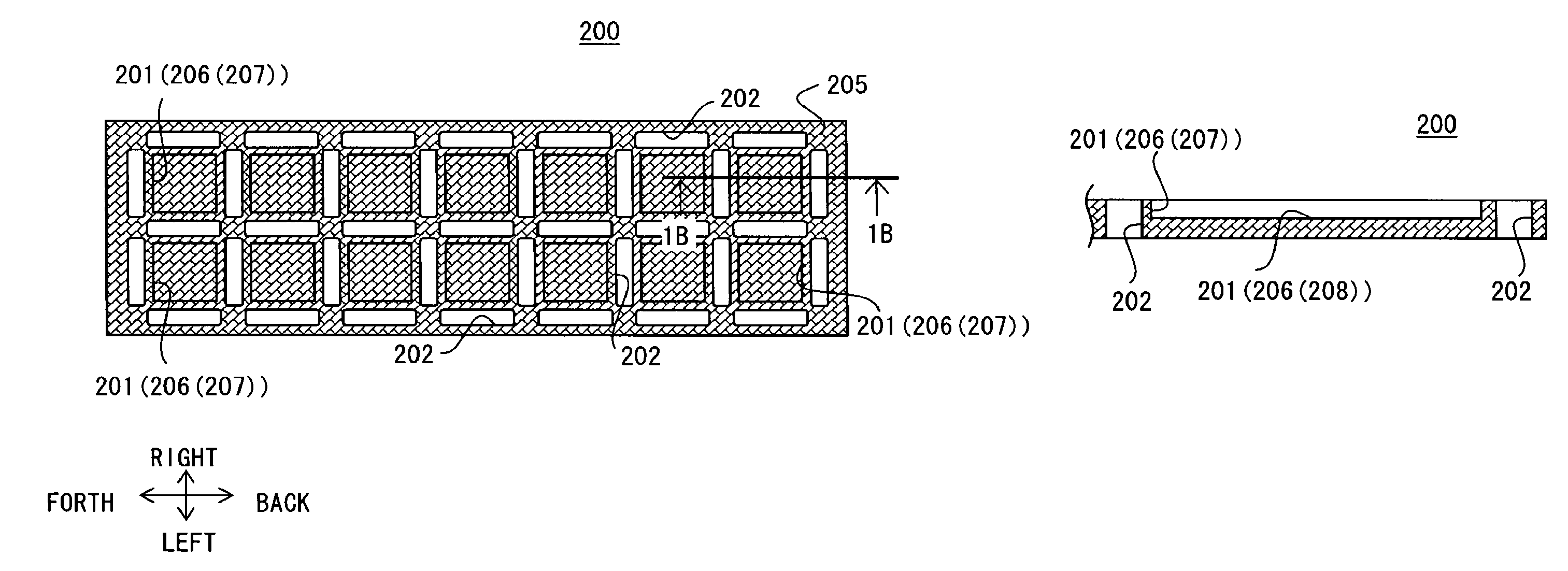
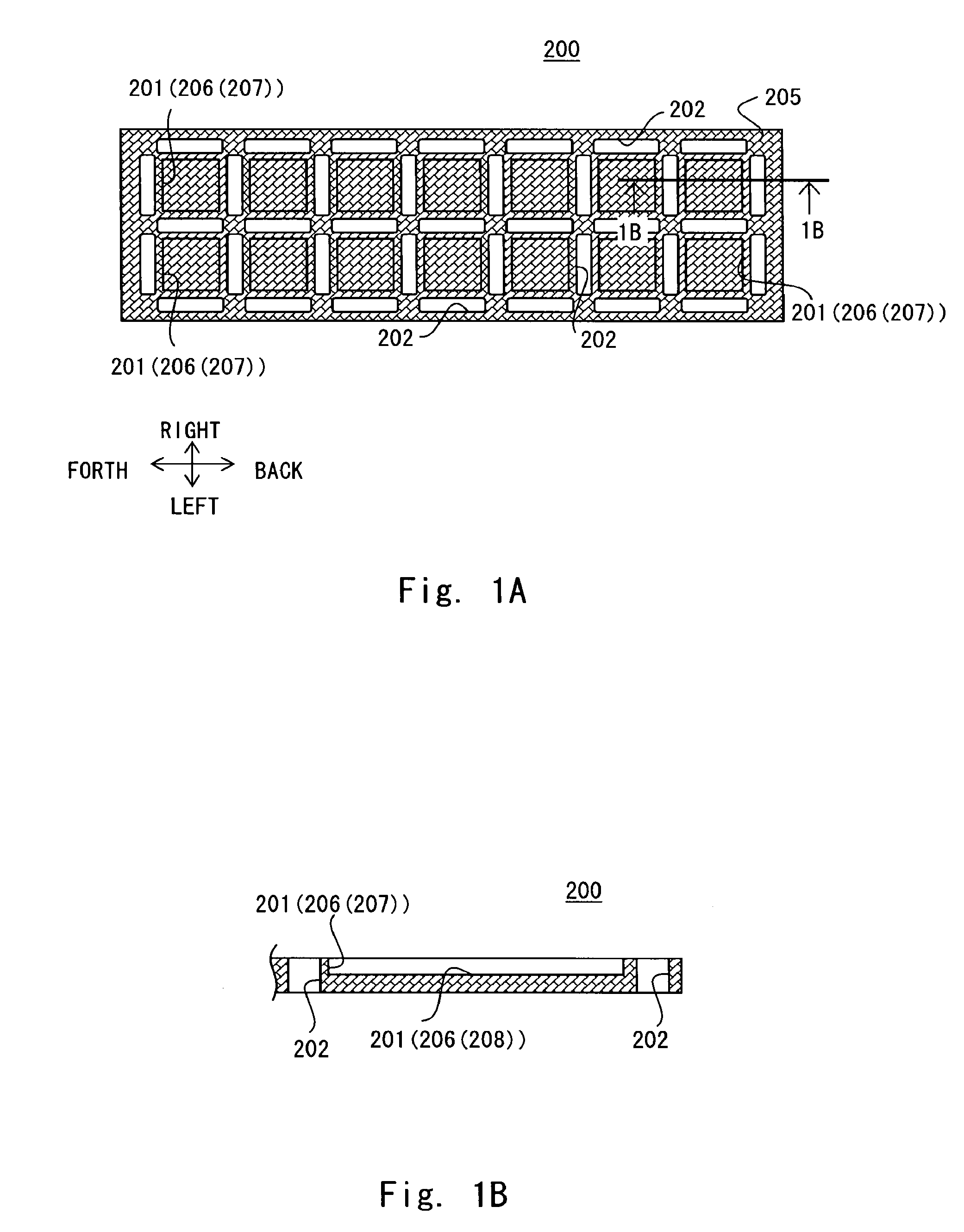
[0107]FIG. 1A is a schematic top view of a heat treatment jig 200 according to an embodiment of the present invention. FIG. 1B is a cross sectional diagram showing the cut section taken along the line 1B-1B of FIG. 1A. In the explanation hereinafter, for convenience of explanation, back, forth, left, right, top and bottom directions are defined as indicated by the arrows in FIG. 1A. The heat treatment jig 200 shown in FIG. 1A includes a rectangle substrate 205 with its sides in back and forth directions indicated by the arrows in FIG....


PUM

PropertyMeasurementUnit
thicknessaaaaaaaaaa
areaaaaaaaaaaa
resistanceaaaaaaaaaa

Abstract

A heat treatment jig includes a holding concave portion to hold an object and a void part formed near the holding concave portion and a thermal history variation of the object in a heat treatment process is reduced thereby.

Description

BACKGROUND OF THE INVENTION[0001]1. Field of the Invention[0002]The present invention relates to a heat treatment jig mounting and holding an object and a heat treatment jig set having the heat treatment jig and a jig cover mounted to the top face thereof.[0003]2. Description of Related Art[0004]In a manufacturing process of a semiconductor device, there is a step of jointing semiconductor components (semiconductor chip, chip capacitor and chip resistor or the like) with wiring board, jointing a pair of semiconductor devices or semiconductor components (a pair of semiconductor chips etc.) (hereinafter also referred to as a pair of semiconductor components) using jointing medium such as solder and adhesive.[0005]One of the jointing methods is that a pair of semiconductor components or the like is mounted and held to a heat treatment jig and the pair of semiconductor components having jointing parts contacting one another is given a heat treatment by a reflow oven. FIG. 30 is a schema...

Claims


Application Information

Patent Timeline
Patent Type & Authority Patents(United States)
IPC IPC(8): F27D5/00
CPCF27D5/0037H01L24/97H01L21/673H01L2224/45144H01L2224/16H01L2224/73265H01L2224/16245H01L2224/48227H01L2224/48465H01L2224/73204H01L2924/00H01L2924/00011H01L2924/00014H01L2924/181H01L2224/0401H01L21/324
Inventor EJIMA, DAISUKEKIDA, TSUYOSHI
Owner RENESAS ELECTRONICS CORP
Features
  • Generate Ideas
  • Intellectual Property
  • Life Sciences
  • Materials
  • Tech Scout
  • Unparalleled Data Quality
  • Higher Quality Content
  • 60% Fewer Hallucinations
Learn More