Multiple-FSR DPSK demodulator

a demodulator and multi-fsr technology, applied in the field of telecommunications differential phaseshift keying (dpsk) can solve the problems of difficult and expensive to achieve, interference between beams from the two channels, and limited operation of each device in a single free spectral rang

Inactive Publication Date: 2011-08-23
OPTOPLEX CORP
View PDF7 Cites 4 Cited by
  • Summary
  • Abstract
  • Description
  • Claims
  • Application Information

AI Technical Summary

Benefits of technology

[0017]Two additional components are preferably used to achieve thermal stability. A temperature-tuned phase shifter is placed in the reflection or the transmission arm to tune the phase of the DLI. A micro-heater is incorporated into the tuner to vary its temperature as necessary to phase tune the DLI. An ambient temperature compensator, preferably a plate made of the same material as the phase shifter, is used in the other arm of the interferometer to compensate for the thermal drift in the phase tuner introduced by the environment.

Problems solved by technology

After the recombination, the beams from the two channels interfere constructively and destructively.
This is difficult and expensive to achieve, especially for an interferometer with a long optical path.
The two beams in each pair interfere, both constructively and destructively, to produce two output beams O1 and O2 that are 180 degrees out of phase.
These demodulators provide a significant improvement over the prior art, but the operation of each device is limited to a single free spectral range.

Method used


Image

  • Multiple-FSR DPSK demodulator
  • Multiple-FSR DPSK demodulator
  • Multiple-FSR DPSK demodulator

Examples


Embodiment Construction

[0027]The invention is described throughout with reference to a Michelson interferometer. However, it is equally applicable to any free-space delay line interferometer. Therefore, the invention is intended to be so construed and it should not be limited to any particular form of interferometer configuration.

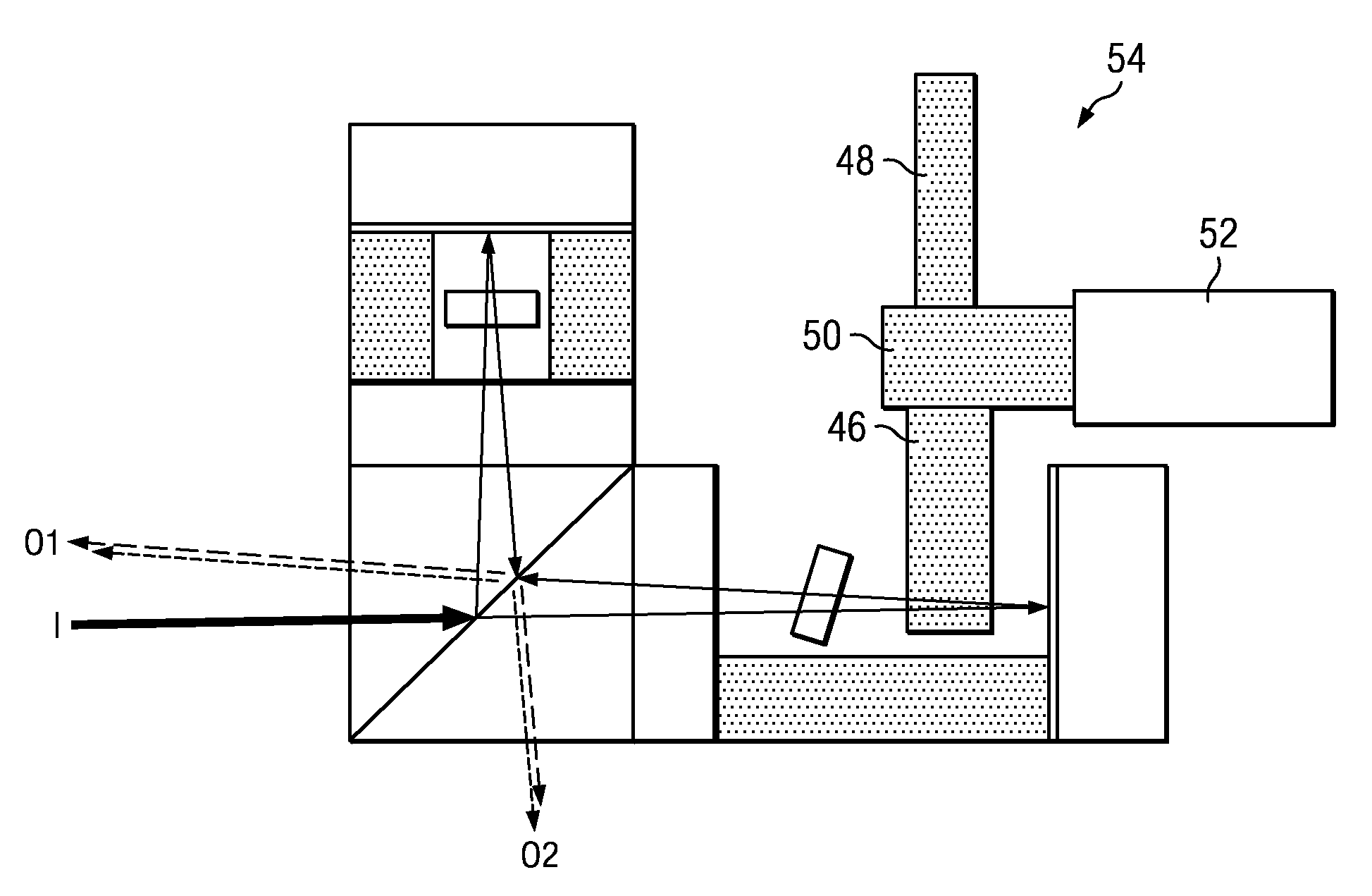
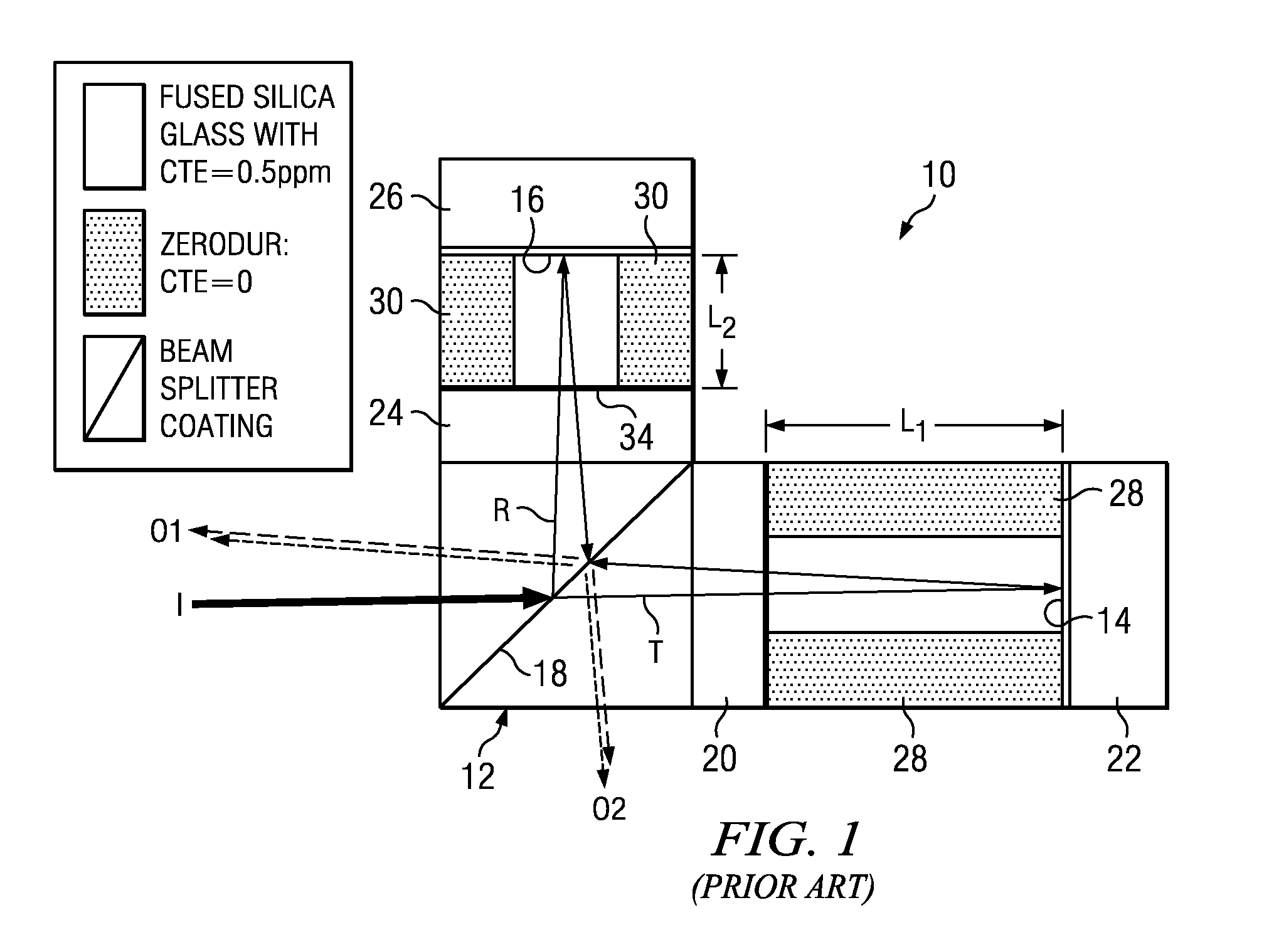
[0028]Referring to the figures, wherein like reference numerals and symbols are used throughout to refer to the same components, FIGS. 3A and 3B illustrate schematically a multiple free-spectral-range DPSK demodulator 40 according to the invention. The device, described in Michelson configuration for illustration, is the same as the Michelson interferometer of FIG. 1, but modified to allow the introduction of a transparent slab 42 in one of the cavities to change the OPD so as to obtain a predetermined alternative free spectral range for the demodulator. In the example, the cavity in the transmission arm of the interferometer is illustrated with an open end that permits the intro...


PUM

PropertyMeasurementUnit
optical path differenceaaaaaaaaaa
transmissionaaaaaaaaaa
transparentaaaaaaaaaa

Abstract

A switchable free-spectral-range mode selector is used to change the free spectral range of a free-space delay-line interferometer. The mode selector consists of a rotatable device with at least one transparent plate selected to produce the desired change in the free spectral range of the delay-line interferometer. The device may be rotated in and out of the free-space optical path of on of the interferometer arms. If used as a DPSK demodulator, the device enables operation at multiple predetermined free spectral ranges. In the preferred embodiment, the demodulator includes a 50/50 beam-splitter cube combined with two cavities. The mode selector consists of a plurality of different transparent slabs attached to a rotatable shaft so that any one of the slabs or none may be inserted in the appropriate optical path to obtain the desired FSR mode of operation.

Description

RELATED APPLICATIONS[0001]This application is based on and claims the priority of U.S. Provisional Application Ser. No. 61 / 094,966, filed Sep. 7, 2008.BACKGROUND OF THE INVENTION[0002]1. Field of the Invention[0003]This invention relates to differential phase-shift keying (DPSK) in telecommunication. More specifically, it relates to DPSK devices for multiple free-spectral-range operation.[0004]2. Description of the Prior Art[0005]Phase-shift keying (PSK) is a digital modulation scheme that conveys data by changing, or modulating, the phase of a reference signal (the carrier wave). Any digital modulation scheme uses a finite number of distinct signals to represent digital data. In the case of PSK, a finite number of phases is used. Each of these phases is assigned a unique pattern of binary bits. Usually, each phase encodes an equal number of bits. Each pattern of bits forms the symbol that is represented by the particular phase. The demodulator, which is designed specifically for th...

Claims


Application Information

Patent Timeline
Patent Type & Authority Patents(United States)
IPC IPC(8): G02F2/00
CPCH04B10/677
Inventor HSIEH, YUNG-CHIEH
Owner OPTOPLEX CORP
Why Eureka
Try Eureka