
Magnetic paint ball gun apparatus

a paint ball gun and magnet technology, applied in the field of magnet couplings, can solve the problems of destroying the gun, destroying the gun, and breaking and marking the person who has been hit, so as to reduce the likelihood of paint ball breaking during such handling, enhance the reliability of the operation of the paint ball gun, and improve the handling of paint balls.

Inactive Publication Date: 2011-08-30
SQUIRE ROB
View PDF55 Cites 3 Cited by
  • Summary
  • Abstract
  • Description
  • Claims
  • Application Information

AI Technical Summary

Benefits of technology

"The invention aims to improve the handling of paint balls within a paint ball gun to prevent them from breaking during handling. It also enhances the reliability of the operation of the gun and achieves this by directly substituting or replacing less effective or reliable prior art components. Additionally, it reduces the complexity of the gun and allows for adjustment of the forces applied to the paint ball during various operations."

Problems solved by technology

When the paint ball strikes a competitor, it will break and mark the person who has been hit.
Unfortunately, it is also known that many factors can affect the characteristics of the paint ball outer membrane, including but not limited to such diverse factors as temperature, humidity, manufacturing tolerances, production or post-production handling, and the like.
Otherwise, paint balls may break inside the gun, even prior to firing.
When a paint ball does break, the gun may be disabled until the competitor cleans out both the paint and the gelatin capsule.
When this occurs deep inside the gun, the time required for cleaning may be too great, leaving the competitor defenseless against another competitor.

Method used


Image

  • Magnetic paint ball gun apparatus
  • Magnetic paint ball gun apparatus
  • Magnetic paint ball gun apparatus

Examples


Embodiment Construction

[0030]Manifested in the preferred embodiment, the present invention provides magnetic coupling for components that have not heretofore been so coupled, and which offer substantial synergy and benefit not heretofore contemplated.

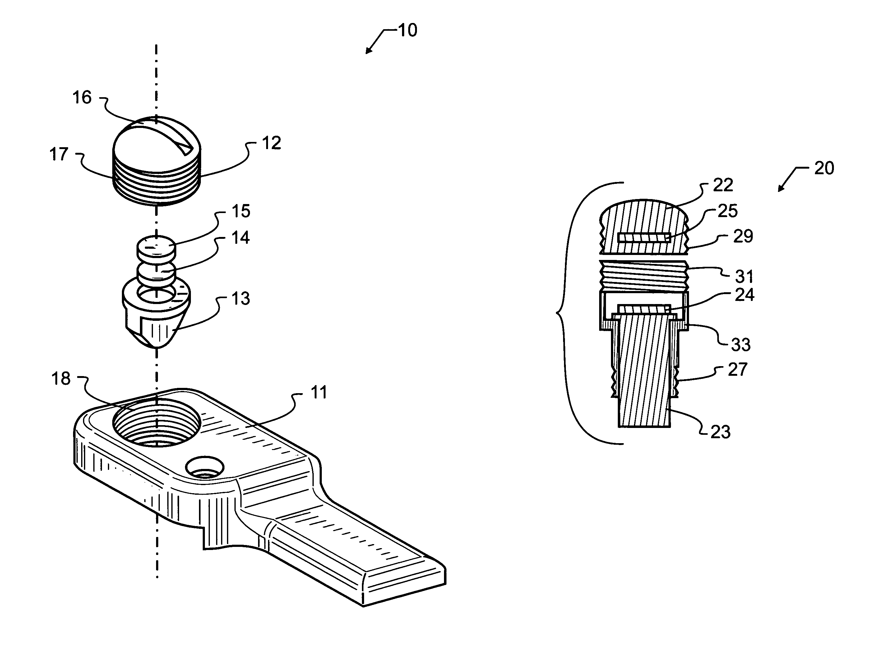
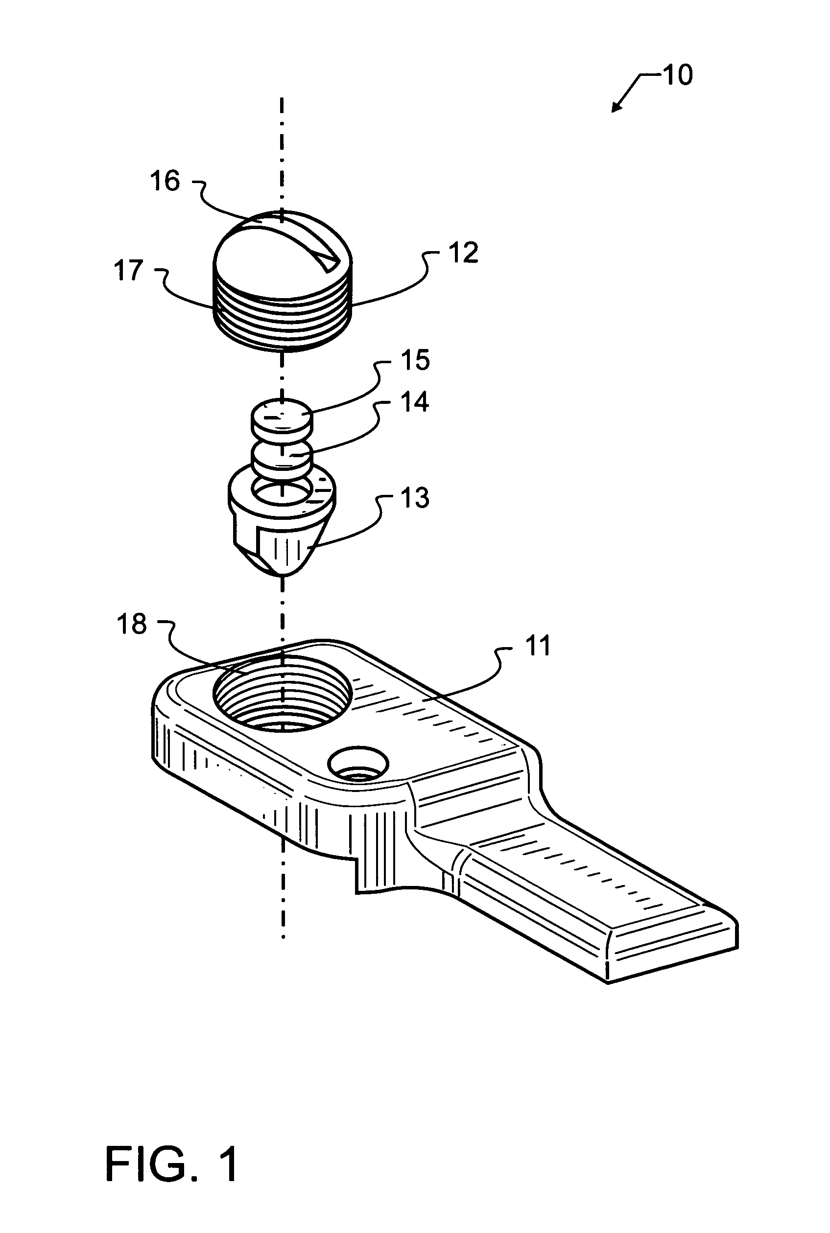
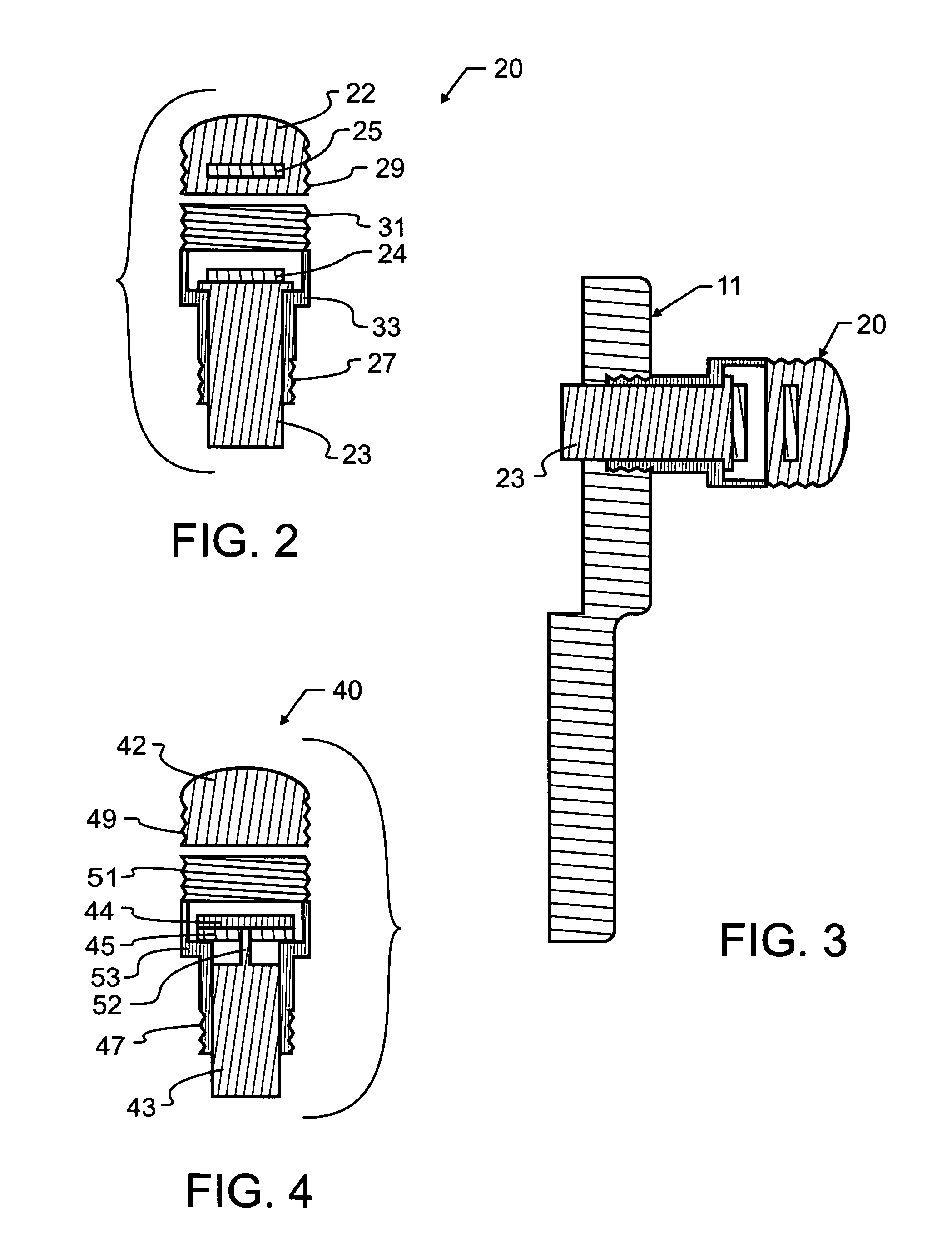
[0031]A most preferred embodiment pin 10 designed in accord with the teachings of the invention is illustrated in FIG. 1. This pin 10 is designed for optimal operation in the barrel of a paint ball gun. As will be known by those familiar with the paint ball gun operation, it may be possible for a paint ball in some instances to inadvertently escape the barrel, or to undesirably migrate towards the open barrel end if not otherwise restricted. The loss of an individual paint ball is relatively minor from an economic standpoint. However, the potential misfire from a mis-positioned ball or the lack of firing during a competition can be most undesirable. The lack of a ball properly placed in the barrel may cause the participant to miss a very important, potentiall...


PUM


Abstract

A paint ball gun barrel indexing pin includes a plunger, cover, body, and first and second magnets that bias the plunger within the barrel. Magnetic coupling is used between rigid components that are used to position paint balls within a paint ball gun. In a “push-push” arrangement, a pair of magnets are oriented with like poles facing each other. When force is applied to one of the pair of magnets, the force will be transmitted through the magnetic fields to the second magnet. This magnetic coupling offers low resistance to movement when the magnets are in an initial substantially spaced apart relationship. Such low force coupling ensures gentle handling of the paint balls. However, as the limits of travel are approached, the magnetic coupling will exponentially increase forces between the magnets, preventing a “bottoming out” of the coupling.

Description

CROSS REFERENCE TO RELATED APPLICATIONS[0001]This application claims priority to U.S. provisional patent application Ser. No. 60 / 581,738 filed Jun. 21, 2004 and entitled “Magnetic Paint Ball Gun Cartridges” by the present inventor, the contents which are incorporated herein by reference in entirety.BACKGROUND OF THE INVENTION[0002]1. Field of the Invention[0003]This invention pertains generally to mechanical guns and projectors, and more specifically to magnetic couplings which offer improved interaction with and operation of paint ball guns. In specific manifestations, magnetic couplings are provided for paint ball indexing, gas valve coupling, magnetically coupled bolts, and custom triggers.[0004]2. Description of the Related Art[0005]Paint ball guns have enjoyed much popularity for a number of years. The sport offers the challenge and intrigue of competitions and battles that stimulate a person's consciousness. However, unlike actual wars, hunts and the like, the combatants may r...

Claims


Application Information

Patent Timeline
Patent Type & Authority Patents(United States)
IPC IPC(8): F41A9/61
CPCF41B11/723F41B11/57
Inventor SQUIRE, ROB
Owner SQUIRE ROB
Learn More