Use of ion implantation in chemical etching

a technology of chemical etching and ion implantation, which is applied in the direction of photomechanical treatment, instruments, electric discharge tubes, etc., can solve the problems of non-uniform copper oxide layer, achieve high ion implantation energy, increase the rate of copper etching per etch cycle, and high ion dose

Inactive Publication Date: 2011-08-30
KLA TENCOR TECH CORP
View PDF40 Cites 6 Cited by
  • Summary
  • Abstract
  • Description
  • Claims
  • Application Information

AI Technical Summary

Benefits of technology

[0023]Ideally, the ions are applied in a sufficient dosage to achieve full formation of the volatilizable compound in this copper layer. For example, one often wants to oxidize copper all the way to cupric oxide (CuO), for which the hfacH etching process is 100% efficient. However, the depth of penetration of the ions at a particular energy has a distribution due to the scattering of the ions by the atoms in the solid. Such scattering often changes the direction of an ion's trajectory, producing a phenomenon called ion straggling. By using a higher ion dose, it is possible to push the formation of CuO to a larger depth. The depth of oxide formation, and therefore the thickness of copper etched, may therefore be controlled by the ion dose. For example, experiments have shown that with 25 kV of O2+, about 25 nm of copper can be etched with 5.5×10¹⁶ / cm2 of dose while about 56 nm of copper can be removed with 1.1×10¹⁷ / cm2 of total dose.
[0026]Each copper etching cycle may comprise an ion implantation step followed by hfacH etching of the volatilizable compound. To increase the rate of copper etching per etch cycle, one may use high ion implantation energy even up to 100 keV as in the SIMOX (separation by implantation of oxygen) process, and high ion doses. To overcome the increased surface roughness after these processes, one may use a low energy glancing angle ion implantation followed by hfacH etching of the oxide to improve the surface smoothness.
[0027]FIG. 3D is a cross-sectional schematic diagram illustrates an example of using glancing incidence to implant the ions into a copper surface. As shown in FIG. 3D the oxygen ions 304 are implanted at asperities 312 and 314 of a copper surface 306 at an angle A. The ion surface density is higher at the asperities surfaces 312 and 314 than other areas of the surface 306. As a result, copper could be removed more readily at those locations in the hfacH etching process, which improves the smoothness of etched surface 306. The glancing-angle θ could be adjusted between 15° and 45° during the ion implantation to optimize the smoothness of the etched surface. The ion energy is preferably sufficiently low so that oxidization mostly takes place at the asperities on the surface. This may also minimize oxidation below the mask and therefore minimize undercutting during etching.
[0034]Using glancing-angle ion bombardment for surface modification rather than conventional near-normal incidence ions has the advantages of preferentially removing surface asperities leading to flat surfaces.

Problems solved by technology

The three-dimensional structures cause the copper oxide layer to be non-uniform.

Method used


Image

  • Use of ion implantation in chemical etching
  • Use of ion implantation in chemical etching
  • Use of ion implantation in chemical etching

Examples


Embodiment Construction

[0016]Although the following detailed description contains many specific details for the purposes of illustration, anyone of ordinary skill in the art will appreciate that many variations and alterations to the following details are within the scope of the invention. Accordingly, the exemplary embodiments of the invention described below are set forth without any loss of generality to, and without imposing limitations upon, the claimed invention.

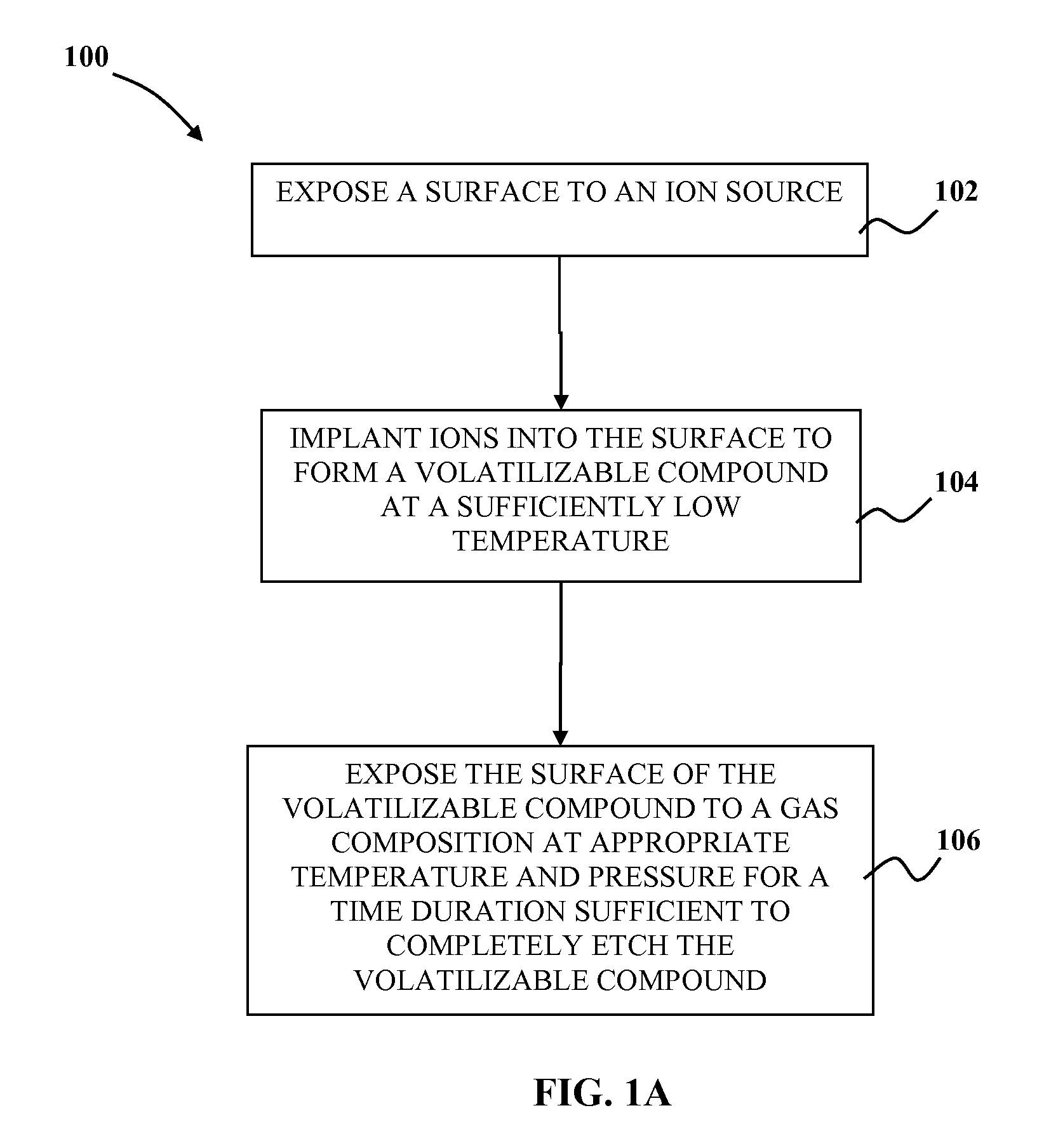
[0017]FIG. 1A illustrates a method 100 for controlling chemical dry etching to improve smoothness of an etched surface according to a preferred embodiment of the present invention. At 102, a surface of a non-volatilizable material is exposed to an ion source. Exposing the non-volatilizable material to the ion source may involve exposure of all or nearly all of the surfaces to the ions. Alternatively only selected portions of the surface may be exposed to the ions. For example, a mask or patterned resist may cover certain portions of the surf...


PUM


Abstract

A method for controlling chemical dry etching to improve smoothness of an etched surface is disclosed. Ions are implanted into a surface to form a volatilizable compound at a temperature low enough to avoid, reduce, or eliminate formation of three-dimensional structures of the volatilizable compound that might create the roughness at an etched surface of the volatilizable compound. The ions are applied in a sufficient energy to penetrate to a predetermined depth of material that is to be removed from the surface in an etching cycle, and in a sufficient dosage to achieve full formation of the volatilizable compound. The surface of the volatilizable compound is exposed to a gas composition for a time duration sufficient to completely etch the volatilizable compound.

Description

CROSS REFERENCE TO RELATED APPLICATION[0001]This application is a continuation-in-part of and claims the benefit of priority of U.S. patent application Ser. No. 11 / 622,625, which was filed on Jan. 12, 2007, the entire disclosure of which are incorporated herein by reference. U.S. patent application Ser. No. 11 / 622,625 claims the benefit of priority to U.S. Provisional Patent Application Nos. 60 / 758,818, filed Jan. 12, 2006, 60 / 829,636, 60 / 829,643, 60 / 829,659 filed Oct. 16, 2006. This application claims the benefit of priority of provisional applications 60 / 758,818, 60 / 829,636, 60 / 829,643, 60 / 829,659, the disclosures of all of which are incorporated herein by reference.[0002]This application is also continuation-in-part of and claims the benefit of priority of U.S. patent application Ser. Nos. 11 / 622,605 now U.S. Pat. No. 7,879,730, 11 / 622,758, now U.S. Pat. No. 7,709,792, 11 / 622,793 now U.S. Pat. No. 7,945,086, and International Application PCT / US2007 / 060503, all filed Jan. 12, 2007...

Claims


Application Information

Patent Timeline
Patent Type & Authority Patents(United States)
IPC IPC(8): H01L21/302H01L21/461
CPCG03F7/2043G03F7/2059H01L21/02057H01L21/3065H01L21/31116H01L21/32136H01J2237/31732H01J2237/3174H01J2237/31744
Inventor YU, MING LUNNASSER-GHODSI, MEHRAN
Owner KLA TENCOR TECH CORP
Why Eureka
Try Eureka