Component with a detection structure for mechanical damage

a detection structure and component technology, applied in the field of components, can solve problems such as significant changes in the electrical properties of electrical conductors, and achieve the effect of easy verification

Inactive Publication Date: 2011-08-30
SIEMENS AG
View PDF16 Cites 5 Cited by
  • Summary
  • Abstract
  • Description
  • Claims
  • Application Information

AI Technical Summary

Benefits of technology

[0010]It is provided that the particles consist of an electrically insulating core with a metallic shell. This means that, even if the metal melts, a structure of the resulting electrical conductor is produced which is not solidly constituted but, but in addition to the pores formed between the particles, also has sub-regions which are filled by the electrically insulating core material of the particles. The resulting sponge-like structure of the conductor also advantageously develops a particular sensitivity to mechanical damage.
[0011]In addition, it is provided that the core consists of a material that is matched to the material of the component in respect of its mechanical behavior, in particular of its thermal expansion behavior. Particularly in the case of thermally stressed components such as heat shield panels, the advantage of this is that electrical conductors placed inside the component exhibit a thermal expansion behavior matched to the thermal expansion behavior of the surrounding component. This enables stresses that would occur due to differential thermal expansion of two different materials, and could result in mechanical overloading of the component, to be avoided. In general, metallic materials have, for example, a higher coefficient of thermal expansion than ceramic components, which makes it more difficult to use metallic conductors in ceramic heat shield panels. For example, in addition to stressing a component, differential thermal expansion of component and electrical conductor also causes the measurement result to be obtained by means of the electrical conductor to be falsified if the latter is deformed by the stresses occurring. Therefore, by matching the thermal expansion behavior of electrical conductor and component, the sensitivity of the measurement method can also be improved to the extent that the possibility of measurement errors occurring is reduced. It is particularly advantageous to select an identical material for core and shell, as this ensures optimum matching of the mechanical properties of the electrical conductor and the surrounding component.
[0013]According to a particular embodiment of the invention it is provided that the particles with the metallic surface in the electrical conductor are present mixed with particles totally consisting of an electrically insulating material, in particular the material of the component. This advantageously ensures that the filling degree of metal in the electrical conductor is further reduced. In addition to the pores between the particles or rather any non-metallic cores of the particles, sub-regions are then also present in the electrical conductor which are constituted by the particles consisting wholly of an electrically insulating material. Due to the reduction of the filling degree of metallic material in the electrical conductor, the latter is, according to the mechanism already described, advantageously even more sensitive to mechanical damage, thereby further increasing the sensitivity of the detection structure.
[0014]As already explained, using the detection structure is particularly advantageous if the mechanical damage to be detected is crack formation in the component, the conductor in this case running such that it is intersected by the likely crack growth. This advantageously ensures that the crack growth, when it has arrived at the surface of the conductor, preferably begins to split the conductor at right angles to its path, thereby producing the greatest possible change in the electrical properties of the conductor in relation to the progressive crack growth. This makes it possible to achieve a change in the electrical properties as soon as the crack has arrived at the conductor used as a detection structure and then progresses further.
[0016]It is particularly advantageous if a plurality of mutually independent conductors is provided which run at different spacings parallel to the surface. This not only ensures timely replacement of the component prior to failure of same, but also enables information about the condition of the component to be obtained at an earlier stage of crack propagation. If mutually independent conductors are present, progressive crack growth will reach adjacent independent conductors one after the other with increasing distance of the crack propagation front from the surface, thereby enabling the present course of the crack propagation front to be assessed.
[0018]According to a particular embodiment of the invention it is provided that the conductor runs in a loop. This can be advantageously placed along the edge of a component of flat design such as a heat shield panel, for example. Moreover, using looped conductors enables particularly characteristic signatures for high-frequency excitation to be produced which also change in an easily verifiable manner due to breakage of the loop in a particular crack growth scenario.

Problems solved by technology

The electrical conductor is therefore rendered conducting by the particles with the metallic surface being in contact with one another so that an exchange of electrons can take place between the particles having the metallic surface, thereby intentionally producing particularly sensitive areas of the electrical conductor at the contact surfaces of the particles, resulting in a significant change in the electrical properties of the electrical conductor in the event of damage to the component (particularly crack growth intersecting the electrical conductor).

Method used


Image

  • Component with a detection structure for mechanical damage
  • Component with a detection structure for mechanical damage
  • Component with a detection structure for mechanical damage

Examples


Embodiment Construction

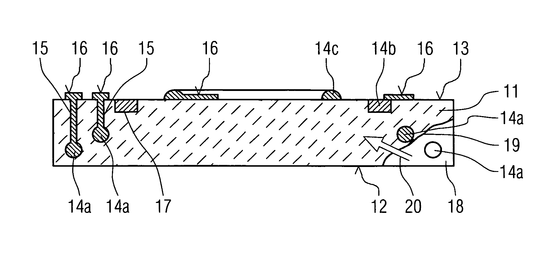
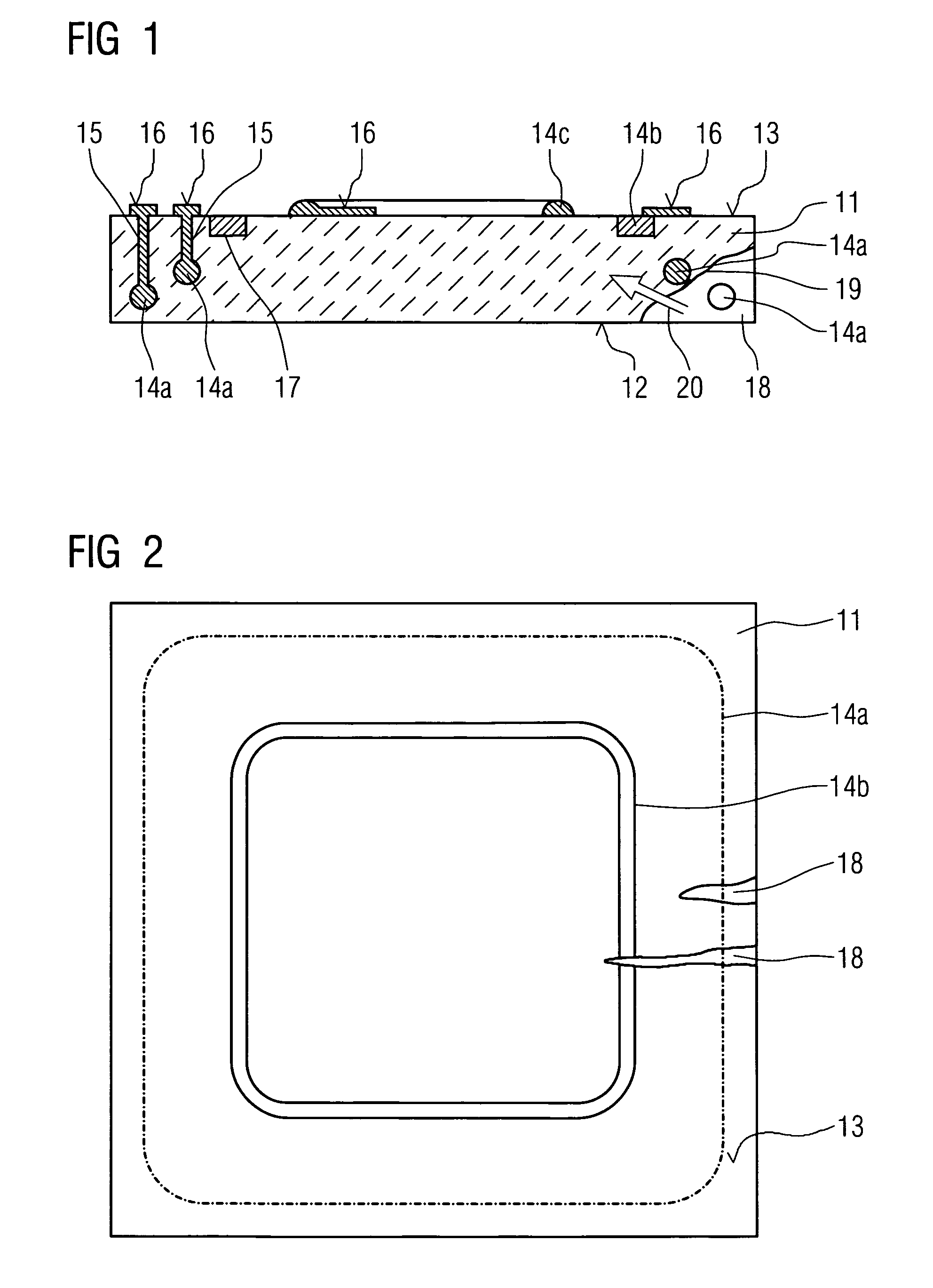
[0024]A component 11, as shown in FIG. 1, is implemented as a heat shield panel e.g. for a gas turbine combustion chamber. This component has a front side 12 facing into the combustion chamber, this side being most heavily subjected to the thermal stress produced by the combustion process, and a back side 13 by which it can be fixed to the wall (not shown in greater detail) of the combustion chamber. The component 11 is made of ceramic. Placed inside the component are electrical conductors 14a which can run in a loop (not visible in the illustration in FIG. 1). These conductors 14a have electrical connections 15 to the back side 13 of the component 11 which are electrically contactable via contact surfaces 16. Accommodated in a groove 17 is another conductor 14b which likewise forms a loop (not shown in greater detail) on the back side 13. There is also implemented on the component surface formed by the back side 13 a raised conductor 14c which likewise runs in a loop. The conductor...


PUM

PropertyMeasurementUnit
electrically insulatingaaaaaaaaaa
electrical propertiesaaaaaaaaaa
thermal expansionaaaaaaaaaa

Abstract

A component made of electrically insulating material with a detection structure for mechanical damage such as cracks is disclosed. The detection structure is a conductor. The electrical properties of the detection structure are modified as more and more cracks are formed such that the component will be replaced in time before breaking. The electrical conductor is formed by particles that are in contact with each other and have a metallic surface such that an electrical conductor is created which is particularly sensitive to mechanical damage, thus rendering the detection structure highly sensitive. Furthermore, if the metallic surface is produced merely by cladding the particles while the inside of the particles is made of the same material as the component, a conductor featuring an adapted thermal expansion behavior is created for components that are subject to great thermal stress, e.g. heat shield panels.

Description

CROSS REFERENCE TO RELATED APPLICATIONS[0001]This application is the US National Stage of International Application No. PCT / EP2007 / 059464 filed Sep. 10, 2007 and claims the benefit thereof. The International Application claims the benefits of German Patent application No. 10 2006 043 781.0 DE filed Sep. 13, 2006, both of the applications are incorporated by reference herein in their entirety.FIELD OF INVENTION[0002]The invention relates to a component of an electrically insulating material incorporating a structure for detecting mechanical damage to the component, the detection structure having an electrical conductor which is fixedly connected to the component and whose geometry is matched to the geometry of the component such that mechanical damage to the component is associated with a change in the electrical properties of the electrical conductor.BACKGROUND OF INVENTION[0003]A component of the type mentioned in the introduction is described, for example, in DE 102 23 985 A1. The...

Claims


Application Information

Patent Timeline
Patent Type & Authority Patents(United States)
IPC IPC(8): G01R27/08G01N27/00
CPCG01N3/066
Inventor ARNDT, FRANKKRUGER, URSUSSTIER, OLIVER
Owner SIEMENS AG
Why Eureka
Try Eureka