Disk preconditioning apparatus and related method

Active Publication Date: 2011-08-30
SEAGATE TECH LLC
View PDF13 Cites 3 Cited by
  • Summary
  • Abstract
  • Description
  • Claims
  • Application Information

AI Technical Summary

Benefits of technology

[0018]The disadvantages of prior techniques are overcome by the apparatus and techniques of the present invention in which two substantially identical, but opposing, pancake coils are disposed generally parallel to one another with a gap therebetween into which a disk to be preset is inserted. A large pulse of current is delivered to the coils to generate a large magnetic field. More specifically, the radial fields of each respective pancake coil add together in the space in the gap where the disk is located. Outside of the gap region, the fields radiating from each respective pancake

Problems solved by technology

However, demagnetizing fields of the outer and inner edges of a magnetic disk give rise to the formation of complex closure domain structures known as “domain walls” which can interfere with the storage medium flux and result in a phenomenon as “spike noise.” Specifically, domain walls form in a soft underlayer between adjacent regions that are magnetized radially outwardly and radially inwardly.
The spike noise can reach the read head and cause errors.
The spike can be approximately 1 micron wide, and can thus affect about 40 bits of data, possibly creating read errors in those 40 bits of data.
These edge fields have perpendicular components that thus interfere with the desired radial pattern of magnetization.
However, in perpendicular magnetic recording media, a DC erase process is disadvantageous due to the density of the cells in which the magnetic domains are contained.
It is particularly harmful in the servo regions.
Thus, a DC erase process is not suitable for preconditioning a disk which is for use in

Method used


Image

  • Disk preconditioning apparatus and related method
  • Disk preconditioning apparatus and related method
  • Disk preconditioning apparatus and related method

Examples


Embodiment Construction

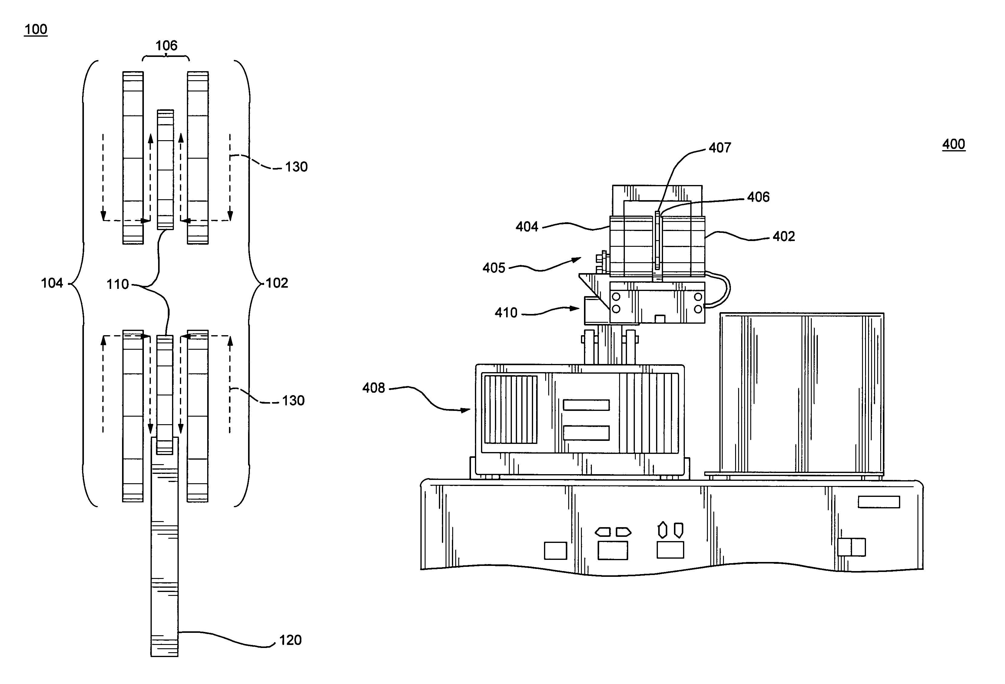
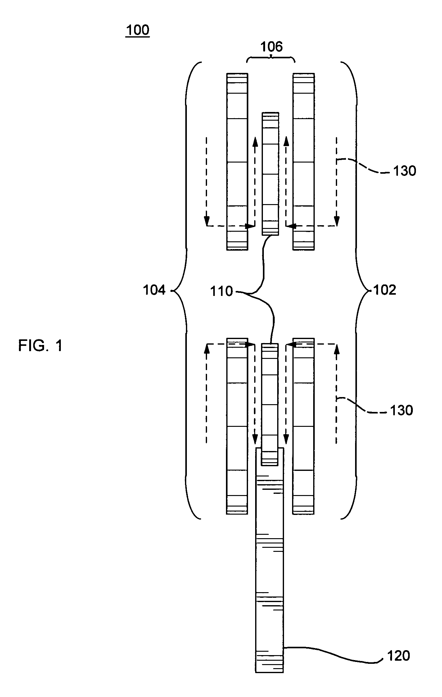
[0031]FIG. 1 is a schematic illustration of a portion the disk preconditioning system 100 of the present invention. The system 100 includes two pancake coils 102 and 104, which are substantially identical in size, but opposed in winding orientation, and which are disposed generally parallel to one another with a gap 106 being defined therebetween. A disk 110 is fixed to a suitable robot arm 120 which moves the disk 110 into the gap 106 between the coils for preconditioning.

[0032]Illustratively, the pancake coils 102 and 104 may have an outer diameter of approximately 4.3 inches or such other dimension as required so that the diameter of the coils exceeds the outer diameter of the disk 110 by at least three times the size of the gap 106. The gap is about 0.25 inches wide in accordance with an illustrative embodiment of the invention. This results in a field of about 85% of the field strength at the inner portion of the disk.

[0033]When a high current pulse is driven to the coils using...


PUM


Abstract

An apparatus and method for preconditioning a magnetic recording disk is provided in which two substantially identical, but opposing, pancake coils are disposed generally parallel to one another with a gap therebetween into which a disk to be preconditioned is inserted. A large pulse of current is delivered to the coils to generate a magnetic field that is sufficiently strong to precondition the disk. The radial fields of each respective pancake coil add together in the gap where the disk is located, and the field presets both the data layer and the hard bias layer of the SUL. Outside of the gap region, the fields cancel one another such that there are essentially no perpendicular fields due to the symmetry of the coils, such that there is very little net residual perpendicular magnetization when the disk is removed from the gap. An electrical circuit for producing the current pulse is provided. An aluminum support structure provides thermal management and magnetic flux conductivity for the system.

Description

CROSS REFERENCE TO RELATED APPLICATION[0001]The present application claims priority from U.S. Provisional Patent Application No. 60 / 735,129, which was filed on Nov. 9, 2005, by Mallary et al., for a DISK PRECONDITIONING APPARTUS, which provisional application is hereby incorporated by reference as though fully set forth herein.BACKGROUND OF THE INVENTION[0002]1. Field of the Invention[0003]This invention relates generally to magnetic recording disks and, more particularly, to preconditioning such disks prior to use thereof.[0004]2. Background Information[0005]Disks used for magnetic recording and storage of data have a number of layers that perform various functions for correctly writing data on the disk, reading data back from the disk, and locating data in the appropriate track on the disk. The composition of the layers of a disk depends upon whether the disk is used for longitudinal recording or perpendicular magnetic recording, for example. The initial magnetization of the layer...

Claims


Application Information

Patent Timeline
IPC IPC(8): H01F13/00H01H47/00
CPCG11B5/0245G11B5/84
Inventor MALLARY, MICHAELPETERSON, DAVID
Owner SEAGATE TECH LLC
Why Eureka
Try Eureka