Suspension board with circuit

a suspension board and circuit technology, applied in the direction of maintaining the alignment of the head carrier, recording information storage, instruments, etc., can solve the problems of unstable position of the slider substrate, inability to reliably bond the substrate, etc., and achieve the effect of improving the connection reliability of the terminal portion

Inactive Publication Date: 2011-09-06
NITTO DENKO CORP
View PDF19 Cites 6 Cited by
  • Summary
  • Abstract
  • Description
  • Claims
  • Application Information

AI Technical Summary

Benefits of technology

It is therefore an object of the present invention to provide a suspension board with circuit which allows a slider to be reliably bonded, and supported in a stable position.
In the suspension board with circuit of the present invention, the lower pedestal is formed in the continuous frame shape, and the upper pedestal is formed in the discontinuous frame shape. The arrangement restricts the outflow of an adhesive coated on the bonding surface from the lower pedestal, and ensures a sufficient amount of the adhesive required for bonding. Conversely, when the adhesive is coated in an excessive amount, the adhesive coated in an excessive amount is allowed to flow out from the discontinuous portion of the upper pedestal. As a result, it is possible to stably place the slider on the pedestal, and reliably bond the slider to the bonding surface. Therefore, the slider can be stably maintained in a steady floating position (angle).
When the cut-away portion of the upper pedestal is one, the adhesive coated in an excessive amount is allowed to flow out only from the one cut-away portion. As a result, it is possible to reduce a wide range of contamination with the adhesive over the suspension board with circuit.
When the cut-away portion is formed in the portion of the surrounding wall opposite to the portion thereof adjacent to the terminal portion, even though the adhesive flows out from the cut-away portion, it is possible to prevent the adhesive from entering the terminal portion. This allows an improvement in the connection reliability of the terminal portion.

Problems solved by technology

Therefore, when the adhesive is expelled in an excessive amount, it may be the case where the slider substrate cannot be reliably bonded to the bonding surface due to the shortage of the adhesive.
As a result, the slider substrate may tilt into an unstable position.

Method used


Image

  • Suspension board with circuit
  • Suspension board with circuit
  • Suspension board with circuit

Examples


example 1

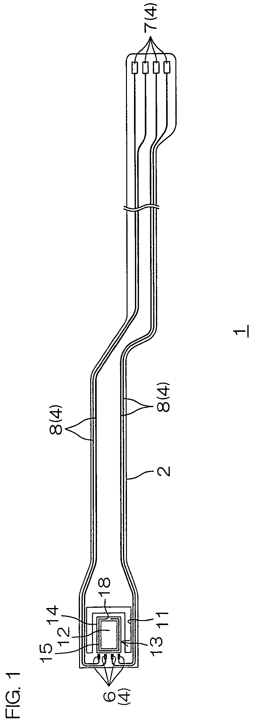
A metal supporting board made of a stainless steel foil with a thickness of 20 μm was prepared (see FIG. 4(a)).

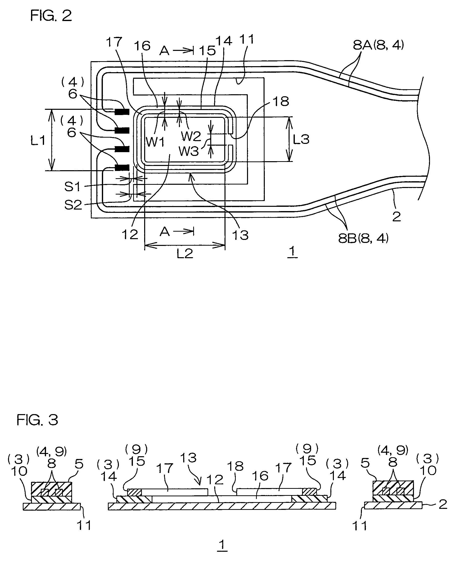
Then, a varnish of a photosensitive polyamic acid resin was coated on the entire surface of the metal supporting board, dried, and exposed to light via a photomask, developed, and then heated to simultaneously form a pattern formation portion and a lower pedestal on the surface of the metal supporting board (see FIG. 4(b)).

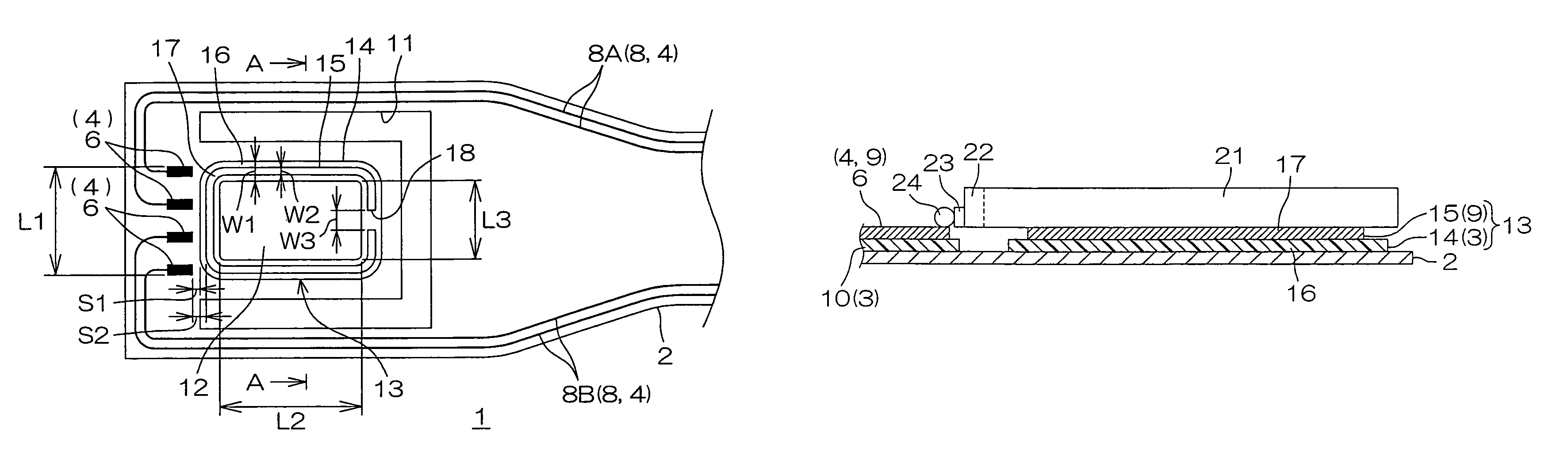
The lower pedestal was formed into a rectangular frame shape from a lower surrounding wall continuously surrounding a bonding surface defined in a generally rectangular shape when viewed in plan view. The longitudinal length L2 of the bonding surface was 0.75 mm, and the widthwise length L3 thereof was 0.55 mm. The width W1 of the lower surrounding wall was 110 μm. The thickness of each of the pattern formation portion and the lower pedestal was 10 μm.

Then, in accordance with an additive method, a conductive seed film made of a chromium thin film with a t...


PUM

PropertyMeasurementUnit
widthwise lengthaaaaaaaaaa
distance L1aaaaaaaaaa

Abstract

A suspension board with circuit includes a metal supporting board, an insulating layer formed on the metal supporting board, a conductive layer formed on the insulating layer, and a pedestal for supporting a slider. The pedestal includes a lower pedestal made of the insulating layer, and formed in a continuous frame shape so as to surround a bonding surface of the metal supporting board to the slider, and an upper pedestal made of the conductive layer, and formed in a discontinuous frame shape on the lower pedestal.

Description

BACKGROUND OF THE INVENTION1. Field of the InventionThe present invention relates to a suspension board with circuit and, more particularly, to a suspension board with circuit mounted in a hard disk drive.2. Description of the Related ArtOn a suspension board with circuit mounted in a hard disk drive, a magnetic head is mounted. Specifically, a slider on which a magnetic head is mounted is mounted on the front end portion of the suspension board with circuit.For example, it is proposed that a bonding surface for bonding to a slider substrate is formed at the front end portion of a suspension, and four rod-shaped spacers having the same thickness are provided so as to spaced-apart from each other at the peripheral end portion of the bonding surface to form a rectangular frame shape surrounding the inner portion of the bonding surface (see, e.g., Japanese Unexamined Patent Publication No. 10-27447).In Japanese Unexamined Patent Publication No. 10-27447, an adhesive is coated on the bo...

Claims


Application Information

Patent Timeline
Patent Type & Authority Patents(United States)
IPC IPC(8): G11B5/48G11B5/60G11B21/21
CPCG11B5/486
Inventor OHSAWA, TETSUYANAITO, TOSHIKIIGUCHI, HIROTOSHI
Owner NITTO DENKO CORP
Why Eureka
Try Eureka