
Method for inspecting optical information recording medium, inspection apparatus, optical information recording medium and recording method

a technology of optical information and recording medium, which is applied in the direction of digital signal error detection/correction, instruments, recording signal processing, etc., can solve the problems of inability of optical disc drives to get the focus servo control or tracking servo control done perfectly, the position of information written on the track and the height of storage layer would change quickly, and the level of storage layer change, etc., to achieve the effect of linear velocity and rotational velocity of optical information storage medium, good ser, and low ra

Active Publication Date: 2011-09-06
PANASONIC CORP
View PDF21 Cites 0 Cited by
  • Summary
  • Abstract
  • Description
  • Claims
  • Application Information

AI Technical Summary

Benefits of technology

This approach enables precise measurement of residual errors, ensuring high-quality read signals and tracking servo stability, even at high linear velocities, while minimizing equipment costs and increasing production yield.

Problems solved by technology

The tracking error is sometimes called a “radial tracking error” and the focus error is sometimes called an “axial tracking error”.
Generally speaking, however, if the rotational frequency of a disc were increased, then the locations on the tracks where the information is written and the levels (i.e., heights) of the storage layer would change quickly due to out-of-plane vibrations, eccentricity, defects, variations in thickness distribution and other shape imperfections of the optical disc.
However, there is a certain limit to the response of the servo control.
That is why if the on-track locations or the levels of the storage layer changed at frequencies that are even higher than the quickest possible response of the servo control, then it would be impossible for the optical disc drive to get the focus servo control or the tracking servo control done perfectly.
As a result, the tracking error signal would have an increased residual error (which will be referred to herein as a “residual tracking error”), thus decreasing the stability of the tracking servo.
That is to say, even if the optical disc drive is performing a tracking servo control appropriately enough, the laser beam may still be unable to follow the tracks perfectly to make the level of the tracking error signal not equal to zero, which is what is called a “residual tracking error”.
However, if the spindle motor of such an inspecting apparatus carried out the inspection while rotating at six times as high velocities as normal BDs, then significant residual focus and tracking errors would be detected from mechanical factors of the inspecting apparatus itself, e.g., vibrations and resonance of the actuator.
Then, it would be impossible to precisely measure the residual errors that have been caused due to the mechanical properties of the optical disc (or get the inspection done) just as originally intended.
Nevertheless, if an expensive high-performance inspecting apparatus that would have reduced vibrations or actuator resonance were newly introduced, then investment on equipment should be newly made, thus eventually increasing the manufacturing cost of the media.
This is a problem because 10,000 rpm is the maximum allowable rotational frequency in practice that was determined from safety considerations in view of the rupture limit of plastic that is the substrate material of the disc.
For that reason, if the servo characteristic of the inspecting apparatus should have an even higher gain intersection to cope with the 6× linear velocity for BDs, then the actuator would have a decreased oscillation or phase margin, thus making it virtually impossible to secure servo stability.

Method used


Image

  • Method for inspecting optical information recording medium, inspection apparatus, optical information recording medium and recording method
  • Method for inspecting optical information recording medium, inspection apparatus, optical information recording medium and recording method
  • Method for inspecting optical information recording medium, inspection apparatus, optical information recording medium and recording method

Examples


Embodiment Construction

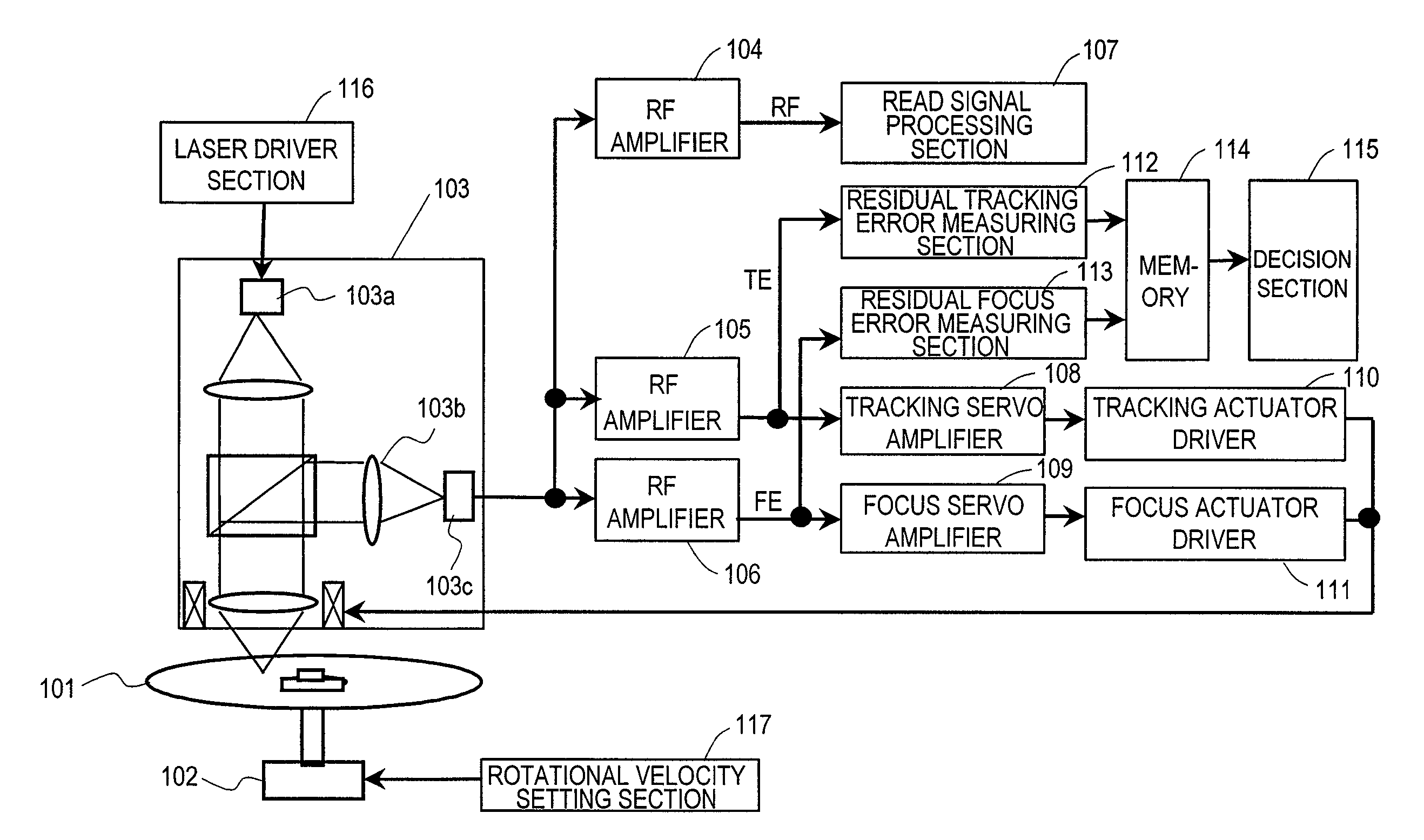
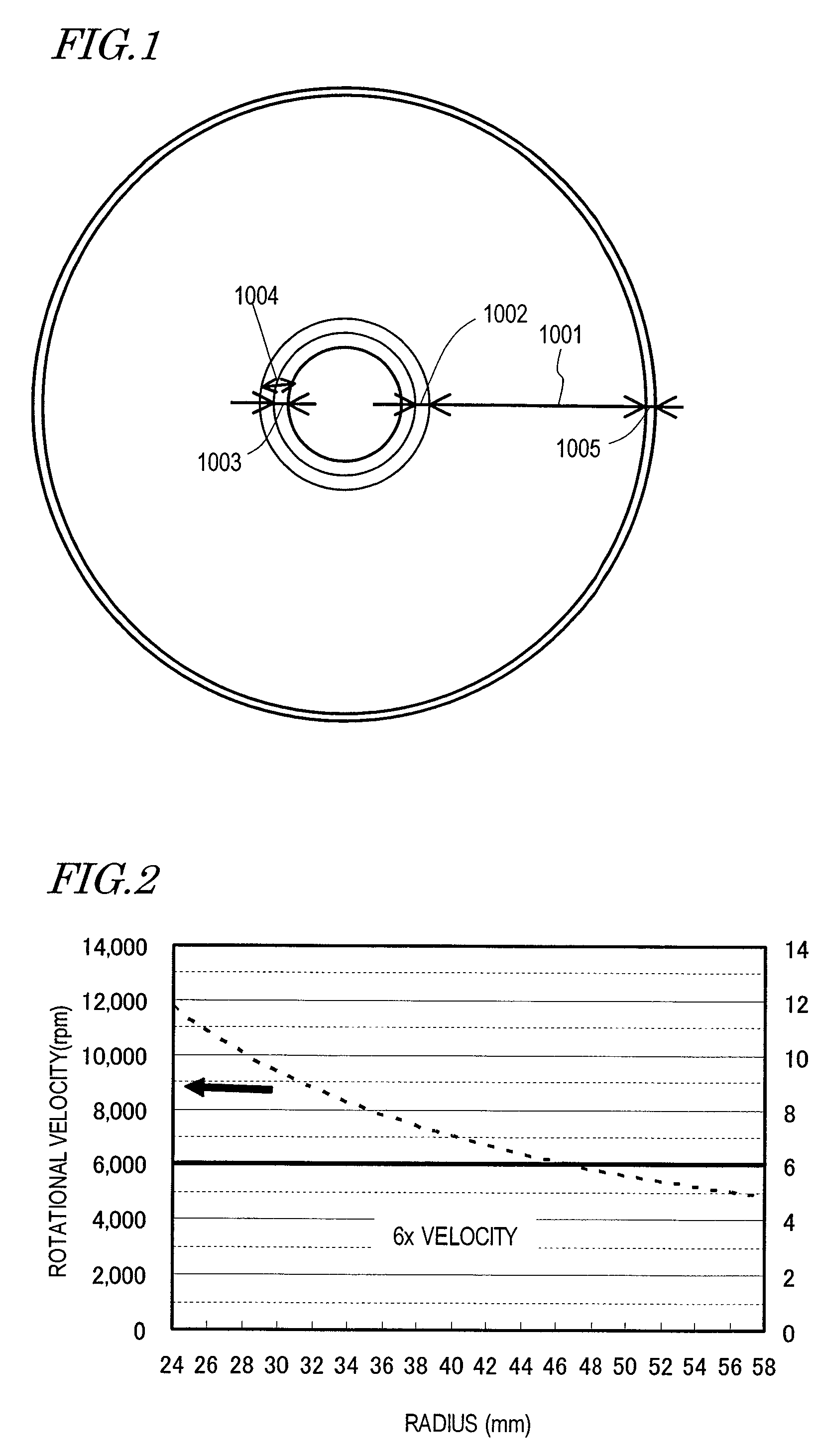
[0056]FIG. 1 illustrates a format for an optical information storage medium having a data area 1001 and a PIC zone 1003, according to a preferred embodiment of the present invention. FIG. 2 shows the relation between the write location and the rotational velocity in a situation where information needs to be read or written from / on a BD-R at 6x linear velocity. The write location is indicated by the radius r. In that case, the BD-R should be rotated at a rotational velocity of approximately 12,000 rpm in the innermost portion (where r=24 mm) of the data area 1001, and at a rotational frequency of approximately 4,800 rpm in the outermost portion of the data area 1001. As can be seen from FIG. 2, however, if a read / write operation is performed on an inner range where the radius r is approximately 28 mm or less, the rotational velocity of the spindle motor exceeds 10,000 rpm.

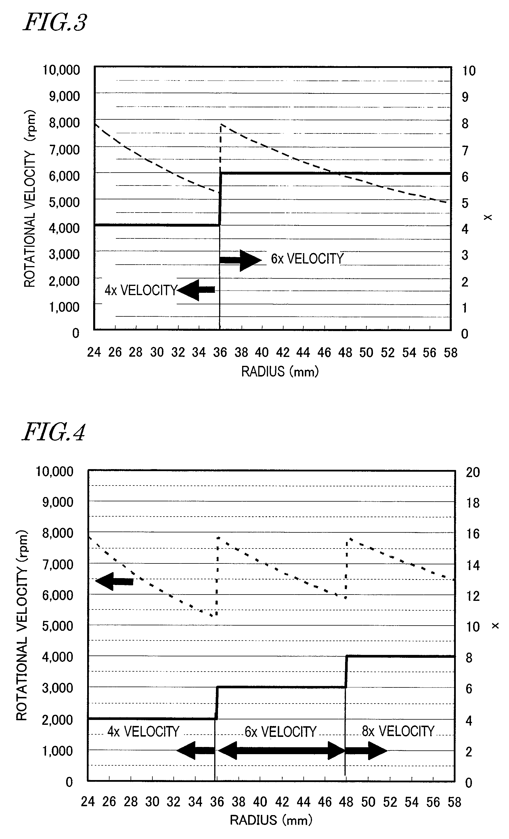
[0057]As described above, the rotational velocity of the optical disc should not be higher than 10,000 rpm consid...


PUM

PropertyMeasurementUnit
linear velocity Lv2aaaaaaaaaa

Abstract

A method for inspecting an optical information storage medium includes irradiating the medium with a laser beam and rotating the medium by a constant linear velocity control technique by reference to the radial location at which the laser beam forms a spot on the medium; changing the rotational velocities according to the radial location on the medium between at least two linear velocities; generating a focus error signal and / or a tracking error signal based on the light reflected from the medium; performing a focus control and / or a tracking control on the laser beam based on the focus and / or tracking error signal(s); and passing the branched outputs of control loops for the focus and / or tracking error signal(s) through predetermined types of frequency band-elimination filters to obtain residual errors of the focus and / or tracking error signal(s) and comparing the residual errors to predetermined reference values.

Description

BACKGROUND OF THE INVENTION[0001]1. Field of the Invention[0002]The present invention relates to a method and apparatus for inspecting an optical information storage medium, an optical information storage medium, and a method of writing information on such a medium. More particularly, the present invention relates to a method and apparatus for inspecting an optical information storage medium on which a read / write operation needs to be performed at high rates and also relates to a method for inspecting such an optical information storage medium for residual focus and tracking errors.[0003]2. Description of the Related Art[0004]An optical information storage medium has a storage layer on which information is written as pits or marks. That information can be read by irradiating the pits or marks with light and by detecting a variation in the intensity of the light reflected. Such an optical information storage medium normally has a disc shape, and therefore, is called an “optical disc”...

Claims


Application Information

Patent Timeline
Patent Type & Authority Patents(United States)
IPC IPC(8): G11B7/00
CPCG11B7/00375G11B7/0079G11B7/268
Inventor NAKAMURA, ATSUSHIFUJIUNE, KENJIHINO, YASUMORI
Owner PANASONIC CORP
Learn More