
High-frequency counter

a counter and high-frequency technology, applied in the field of high-frequency counters, can solve the problems of high power consumption of such a counter, problems such as problems, and other problems, and achieve the effect of reducing the power consumption of the counter and reducing the power consumption

Active Publication Date: 2011-09-06
NXP BV
View PDF13 Cites 2 Cited by
  • Summary
  • Abstract
  • Description
  • Claims
  • Application Information

AI Technical Summary

Benefits of technology

[0010]An object of the present invention is to provide a counter circuit and counter control method, by means of which the above problem of incomplete switching can be solved in a satisfactory manner.
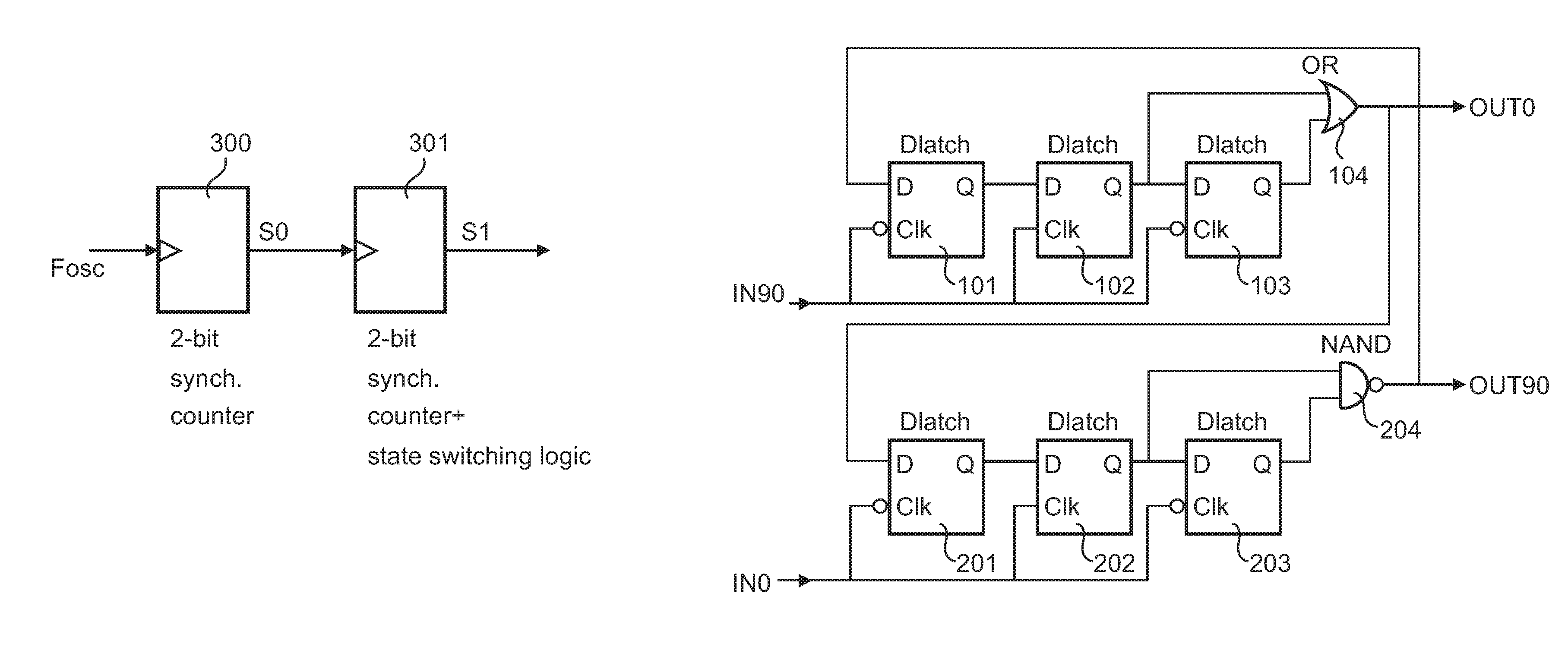
[0012]Accordingly, some redundancy is introduced in the counter, which can be used to detect incomplete switching states of the counter and to output the correct value of the accumulated phase by correcting the error. This correction can be achieved by a simple decoding operation. A counting section that is thus clocked by a previous counting section does not change state when the previous section has completed its full state-cycle, but somewhat earlier (which causes the redundancy), using some extra logic in the counter. Thus, there is a certain overlap in the state rotations of the counting sections. This causes certain states (occurring at the glitches) to be invalid (because they can be shown not to occur if all electronics were delay-free) and these states can be detected. The sampled states can thus be corrected in order to give a correct count value.
[0014]Furthermore, the second counting section may be arranged to change its state one or more states before the first counting section has completed its state-cycle. This ensures that the at least one invalid counting state is introduced in synchronism with the state-cycle and can thus be easily detected.
[0016]The decoder may operate on a sampled output of the complete counter in some applications, including all-digital PLLs, so that its operating speed can be kept low and allows low-speed digital design.

Problems solved by technology

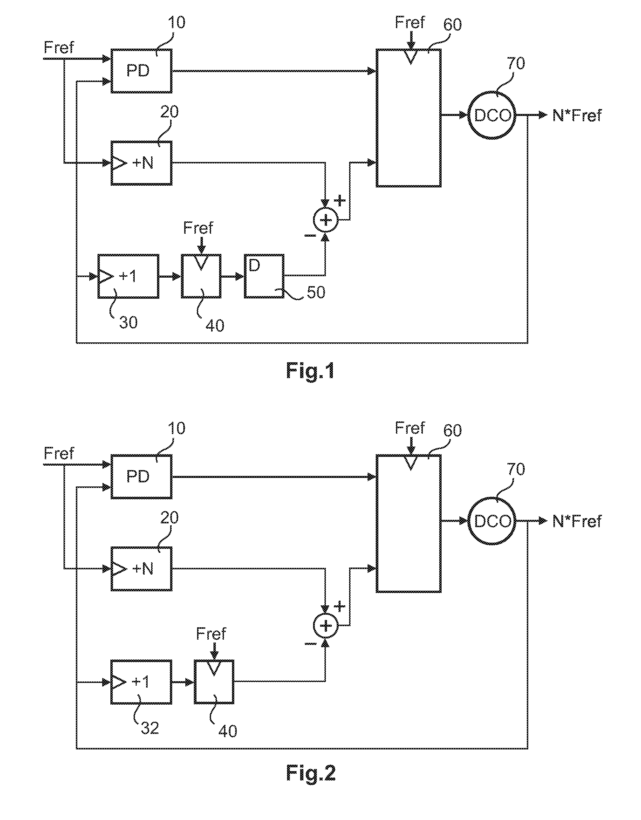
However, when trying to use the +1-counter 32 at high input (oscillator) frequencies NFref, a problem is encountered.
Also, the power consumption of such a counter tends to be high.
On the other hand, if an asynchronous counter topology (where all internal flip-flops change state at different moments in time, e.g., in a ripple counter) is used to overcome these problems, another problem is faced.
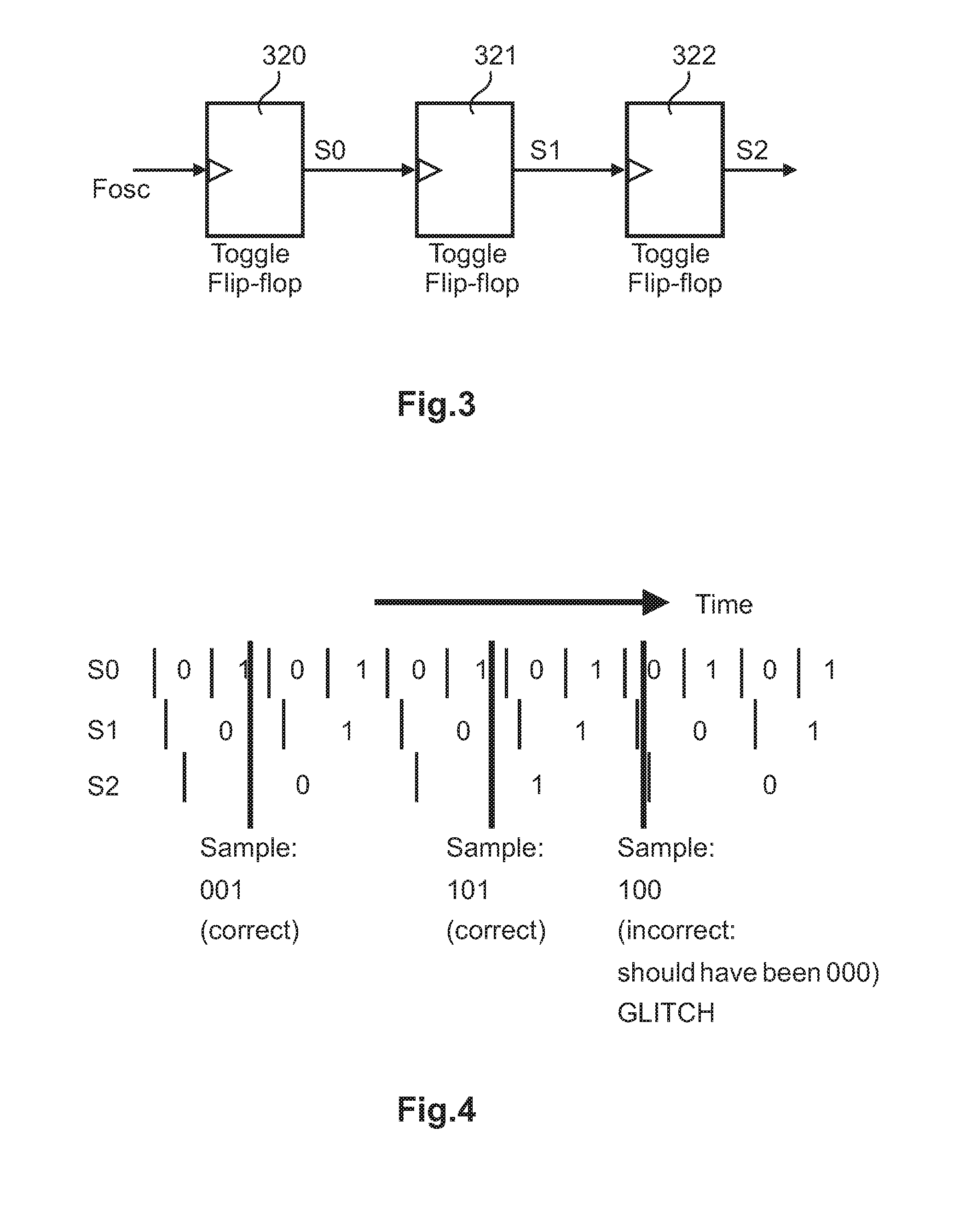
Because the PLL reference signal samples the complete counter output as one single value at a certain moment in time, the first flip-flops in the asynchronous counter may have already changed value, while others did not do so yet, due to internal flip-flop delays, thus causing a completely wrong value to be read out of the counter and causing the PLL to be controlled in the wrong direction.
Using a frequency divider between the oscillator and the counter (thus reducing the input frequency of the counter) does not solve this glitch problem in a satisfactory manner, because the lowered frequency increases the quantization error of the accumulator-based phase detector of FIG. 2 and, with that, the PLL lock time may be increased.

Method used


Image

  • High-frequency counter
  • High-frequency counter
  • High-frequency counter

Examples


Embodiment Construction

[0029]The embodiments of the present invention will now be described in greater detail based on a PLL frequency synthesizer with an all-digital implementation of the PLL circuit.

[0030]In the embodiments, some redundancy is introduced in the counter circuit, which is used to detect incomplete switching of the counter state and to give the correct counting value of the accumulated phase by correcting the error. This correction can be done by using a decoder that is used after the sampler (e.g. register 40 in FIG. 2) driven by the reference frequency Fref and thus at considerably lower speed than the counter itself.

[0031]FIG. 1 shows a schematic block diagram of a PLL based frequency synthesizer according to an embodiment. Those components of FIG. 1, which have identical in reference numerals as those of FIG. 2 have same or similar functionalities and are therefore not explained again for brevity reasons. The proposed +1-counter 30 comprises asynchronously clocked counting sections, wh...


PUM


Abstract

A counter circuit and method of controlling such a counter circuit, including a first counting section that counts in accordance with a state-cycle, and a second counting section clocked by the first counting section. At least one invalid counting state is introduced by controlling the second counting section to change its state before the first counting section has completed the state-cycle; and the invalid counting state is then detected and corrected. Thereby, some redundancy is introduced in the counter, which can be used to detect and correct incomplete switching of counter states.

Description

FIELD OF THE INVENTION[0001]The present invention relates to a transceiver, receiver module, computer program product and method for compensating frequency-dependent delay in a transceiver.BACKGROUND OF THE INVENTION[0002]In communication systems, frequency synthesizers can be used for frequency conversion. Recently, all-digital implementations of phase-locked loop (PLL) circuits (for example to realize frequency synthesizers) have gained a lot of attention. Examples of such all-digital implementations are described for example in R. B. Staszewski et al, “All-Digital TX Frequency Synthesizer and Discrete-Time Receiver for Bluetooth Radio in 130-nm CMOS”, IEEE Journal of Solid-State Circuits, December 2004, and N. Da Dalt et al, “A Compact Triple-Band Low-Jitter Digital LC PLL With Programmable Coil in 130-nm CMOS”, IEEE Journal of Solid-State Circuits, July 2005. In such a PLL, the phase detector is a digital building block, i.e., its output signal is available as a time and amplitu...

Claims


Application Information

Patent Timeline
Patent Type & Authority Patents(United States)
IPC IPC(8): G06M3/00H03K21/40
CPCH03K5/135H03K23/588H03L7/113H03L7/18H03L2207/50
Inventor VAN DE BEEK, REMCO C. H.
Owner NXP BV
Learn More