Wavelength division multiplexed optical channel switching

a multi-channel optical channel and channel switching technology, applied in the field of communication systems and methods, can solve the problems of single point of failure of the optical network at the switch, lower reliability, and higher cost, and achieve the effects of reducing the weight, reducing the cost, and improving the reliability of the optical network

Active Publication Date: 2011-09-06
LOCKHEED MARTIN CORP
View PDF29 Cites 9 Cited by
  • Summary
  • Abstract
  • Description
  • Claims
  • Application Information

AI Technical Summary

Benefits of technology

[0009]Elimination of the OEO switch from designs may enable a system to have one or more of the following advantages: lower weight, smaller volume, higher fault tolerance, elimination of single point of failure of a centralized switch, lower power requirements, lower cost, and higher reliability. Further, improved information (e.g., packetized messages) passing performance may be accomplished according to the present invention because the nodes in a decentralized manner decide which information is to be transmitted and / or received at the various nodes of the network.

Problems solved by technology

However, the brute force method of optical to electrical, and thereafter, electrical to optical conversion, has a number of disadvantages.
Due to the high module density, complex packaging, and higher power implementation of such OEO designs, reliability is negatively affected.
Yet further, there is also a higher cost as a result of the high module density, complex packaging, and high power requirements.
Still further, because all the optical fibers are routed to a centralized (e.g., external to the nodes) switch, a single point of failure for the optical network exists at the switch.

Method used


Image

  • Wavelength division multiplexed optical channel switching
  • Wavelength division multiplexed optical channel switching
  • Wavelength division multiplexed optical channel switching

Examples


Embodiment Construction

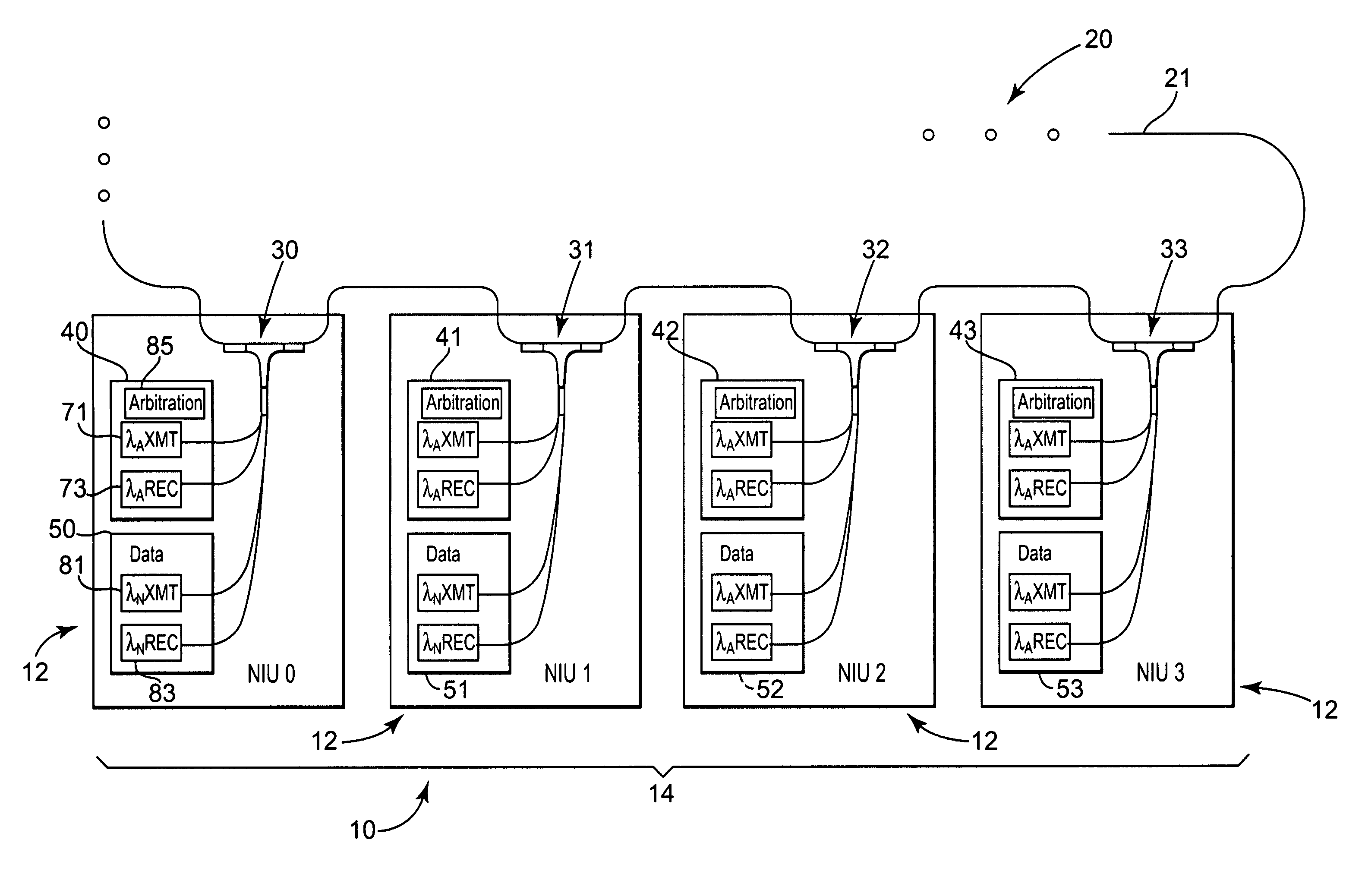
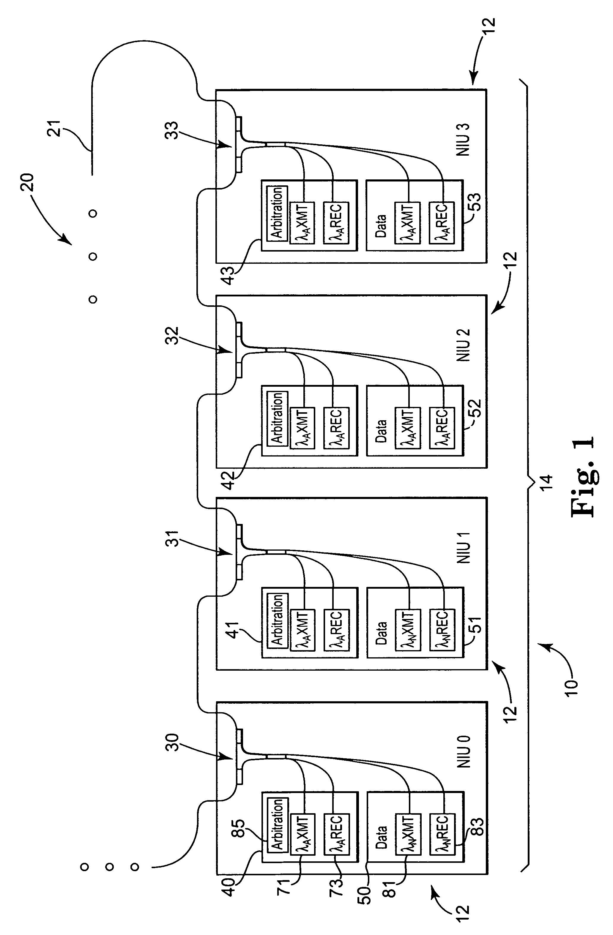
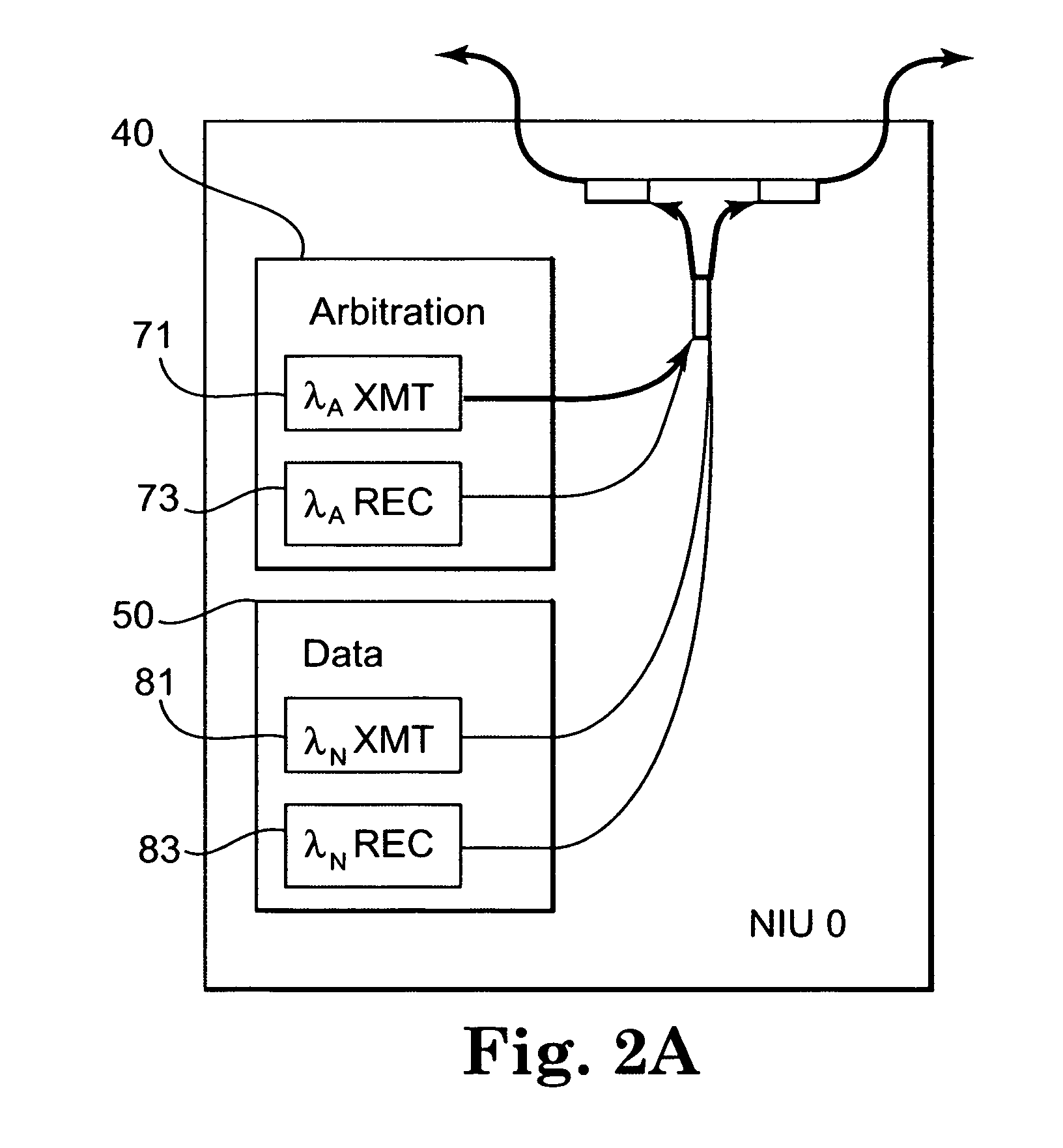
[0024]Generally, an optical communication system 10, according to the present invention, shall be described with reference to FIG. 1. One or more embodiments of the optical communication system and components thereof, along with methods associated with the operation of the optical communication system, shall further be described in more detail with reference to FIGS. 2-4.

[0025]Generally, and as further described herein, optical communication system 10 (e.g., a linear tapped bus) includes a plurality of nodes 14 (e.g., processor nodes) associated with corresponding network interface units (NIUs) 12 (e.g., NIUs connected via input / output to associated processor components). Although FIG. 1 shows network interface units NIU0 through NIU3, it will be readily apparent that any number of NIUs 12 may be used to interface any number of associated nodes 14 to optical backbone 20 of the optical communication system 10. Further, although a linear tapped bus configuration is shown, the present ...


PUM


Abstract

An optical communication system and method for use in communicating data between nodes using wavelength division multiplexing includes an optical backbone to provide an optical pathway between the nodes. Arbitration information on a dedicated arbitration wavelength transmitted during an arbitration cycle is used by the plurality of nodes to select one of a plurality of wavelengths at which to transmit data during a subsequent data cycle.

Description

BACKGROUND OF THE INVENTION[0001]The present invention relates generally to communication systems and methods, and more particularly to optical communication systems and methods. Further, more specifically, the present invention pertains to optical communication systems and methods that employ wavelength division multiplexing.[0002]Optical fiber has been widely accepted as an interconnection medium for communication networks, due mainly to the advantages offered by fiber, such as higher bandwidths and better noise performance, as compared to electrical media. Multi-channel optical networks allow several users to access the fiber simultaneously, thus increasing the overall network capacity. The optical bandwidth may be divided into several channels, each capable of transmitting non-interfering signals at distinct wavelengths, or in other words, wavelength division multiplexed (WDM).[0003]Such an optical network can be used to optically connect any number of nodes having optical trans...

Claims


Application Information

Patent Timeline
Patent Type & Authority Patents(United States)
IPC IPC(8): H04B10/20
CPCH04B10/278H04J14/0227H04J14/0238H04J14/0241H04J14/0228
Inventor STEVENS, RICK C.
Owner LOCKHEED MARTIN CORP
Why Eureka
Try Eureka