

Fluid dispenser head
a dispenser head and dispenser technology, applied in the field of dispenser heads, can solve the problems of difficult manufacturing of dispenser heads and the need for a relatively complicated mold for the endpiece, and achieve the effect of expanding the surface area
- Summary
- Abstract
- Description
- Claims
- Application Information
AI Technical Summary
Benefits of technology
Problems solved by technology
Method used
Image

Examples
Embodiment Construction
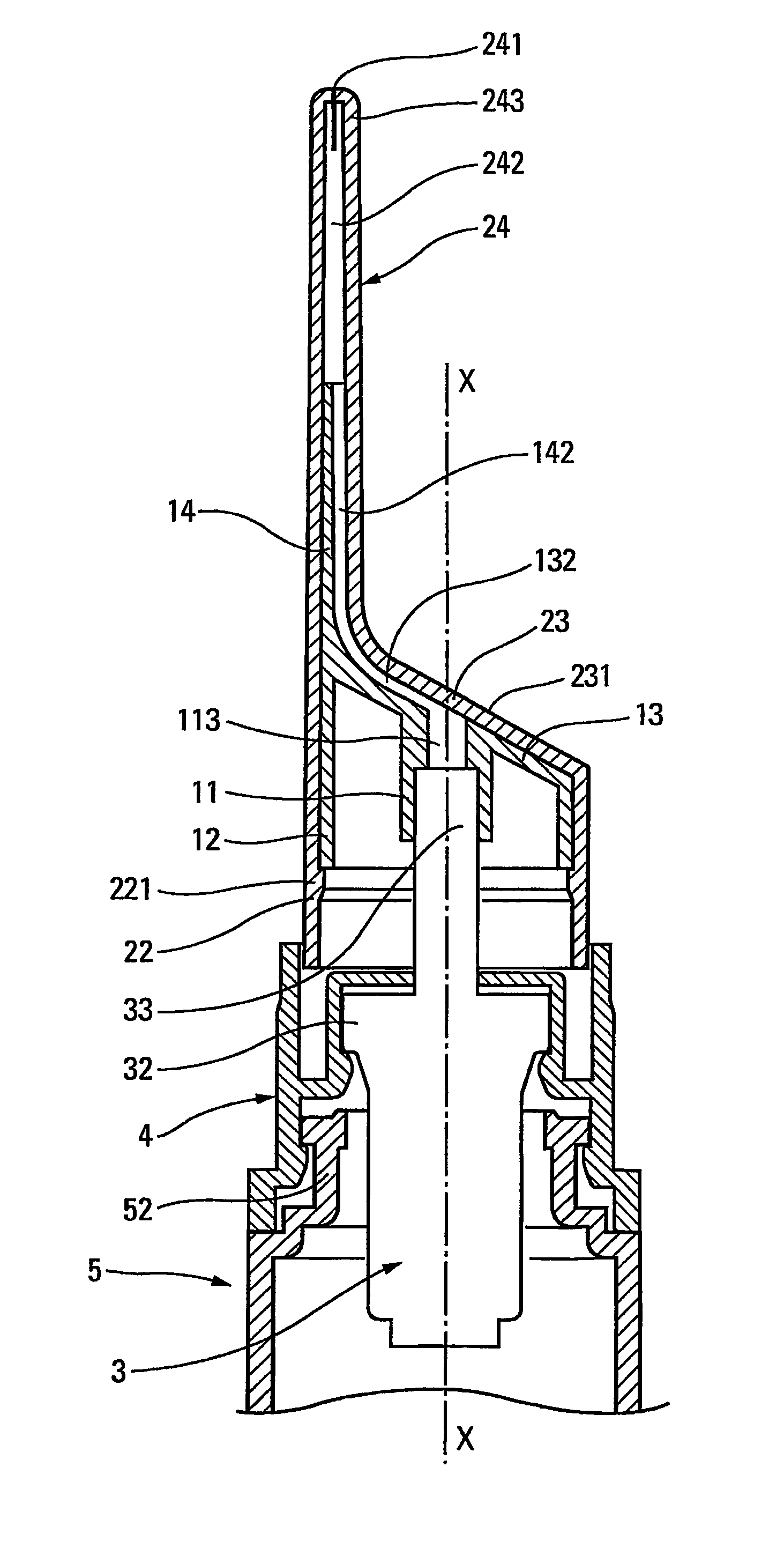
[0005]An object of the present invention is to simplify the manufacture of such a dispenser head. Another object of the invention is to provide the dispenser head with an applicator function for applying fluid to an application surface. Another object is to guarantee preservation of the fluid inside the head, even in the proximity of the dispenser orifice. Another object is to simplify the assembly of such a dispenser head. Another object is to make the dispenser head with as few component parts as possible.
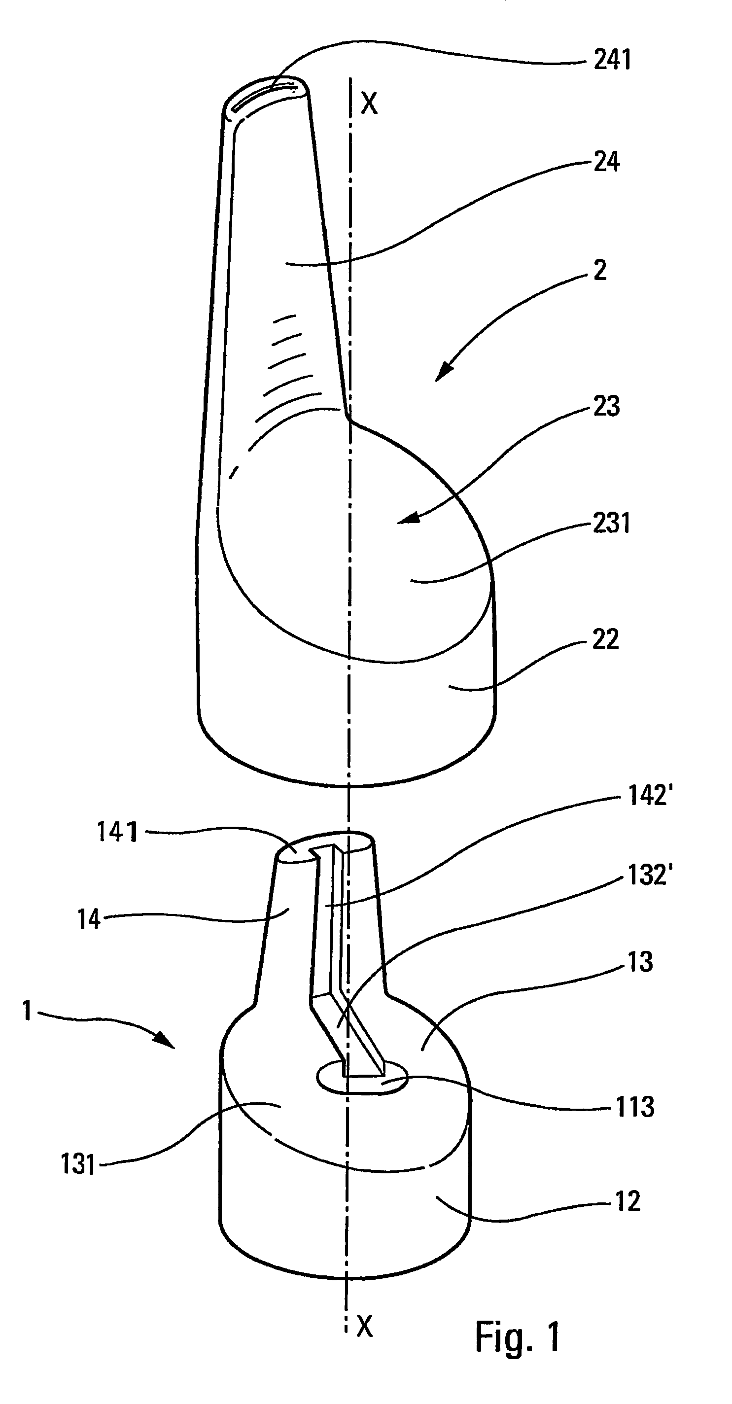
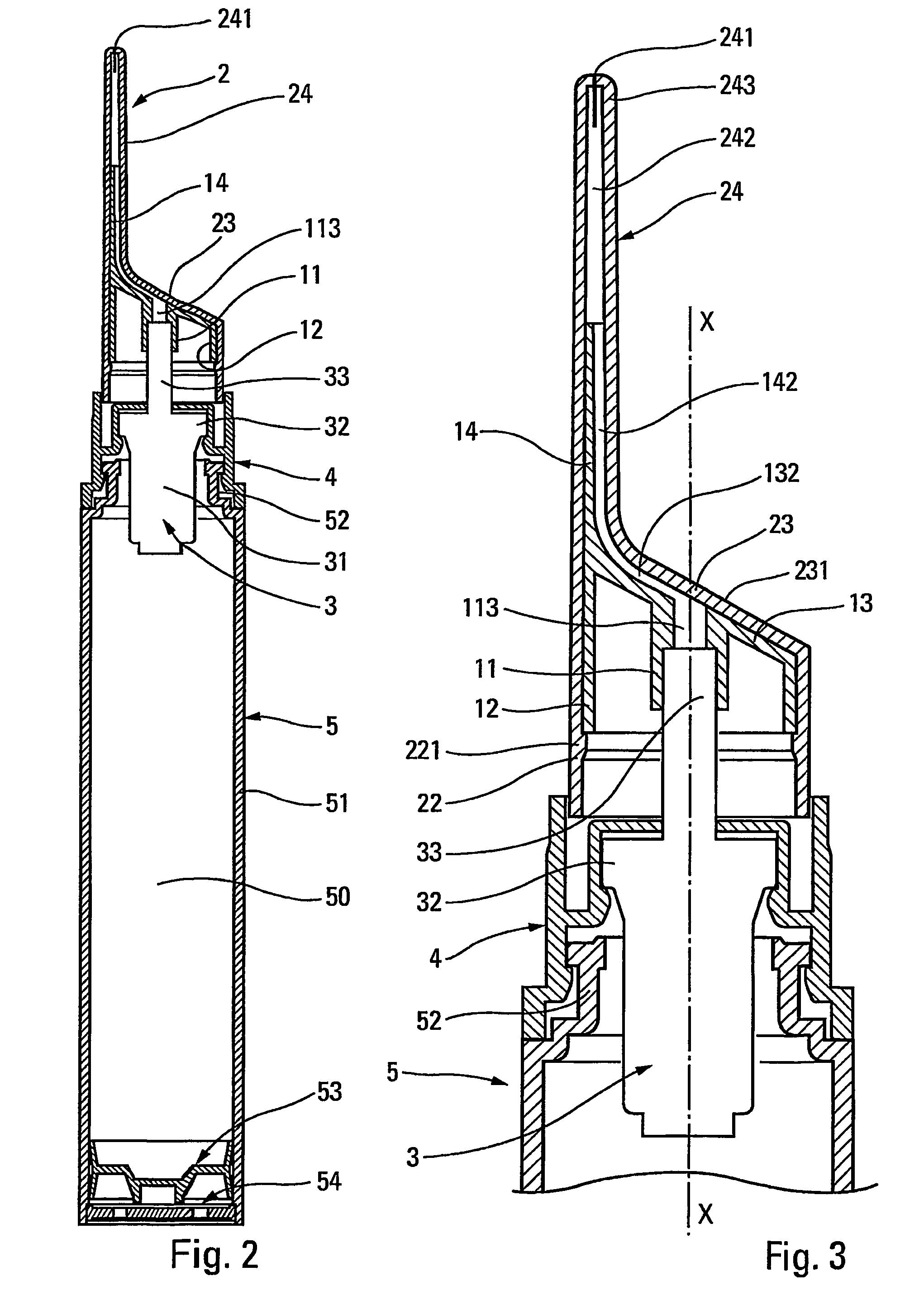
[0006]In order to achieve these objects, the present invention proposes that the endpiece extends substantially parallel to the longitudinal displacement axis of the actuator rod, and is offset away from the axis. Because the endpiece extends parallel to the axis, the dispenser head is easier both to mold and to assemble. The bearing surface can advantageously extend axially downstream from the connection sleeve, intersecting said axis. By offsetting the endpiece, it is possible ...
PUM
 Abstract
Description
Claims
Application Information