Ion trap

a technology of ion traps and traps, applied in the field of ion traps, can solve the problems of increasing requirements, affecting the parameters of the resulting ion beam, and increasing the difficulty of subsequent focusing in this direction

Active Publication Date: 2011-09-13
THERMO FISHER SCI BREMEN
View PDF19 Cites 32 Cited by
  • Summary
  • Abstract
  • Description
  • Claims
  • Application Information

AI Technical Summary

Benefits of technology

[0014]A wider mass range of ions able to be successfully trapped and ejected, because the low mass cut-off of the trap is blurred by the variable gap between the electrodes.
[0015]For the same trap length, a higher space charge capacity. This is due to the ability to better squeeze the ion beam immediately prior to ejection.
[0016]Narrower slits for differential pumping can be used due to the reduced width of the ejected ion beam. This is due to the stronger focusing action able to be produced by the use of, for example, electrodes with differing curvatures.

Problems solved by technology

However, the limited volume of the ion cloud in the traps of this prior art resulted in significant Coulomb interactions between stored ions that greatly affects parameters of resulting ion beams.
However, as the ion cloud is distributed along a substantial length of the trap axis this makes subsequent focusing in this direction problematic.
Firstly, it is complicated to manufacture, secondly, it requires wide slits (with the widths reducing when focal points are approached) leading to increased requirements on differential pumping, and thirdly the trap suffers from the disadvantage that it has a space charge capacity lower than that of the orbitrap itself.
Furthermore, the lenses between the trap and the mass analyser are curved and complex to manufacture and align.
In addition, the mass range of ions that can be accumulated and injected into the mass analyser is limited.

Method used


Image

  • Ion trap
  • Ion trap
  • Ion trap

Examples


Embodiment Construction

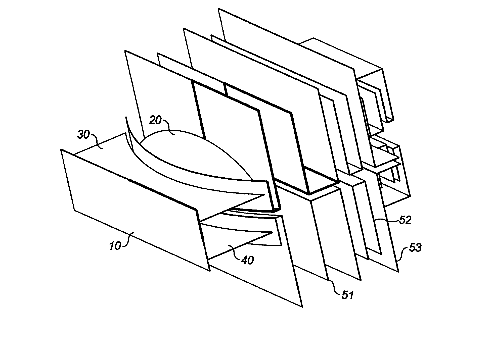
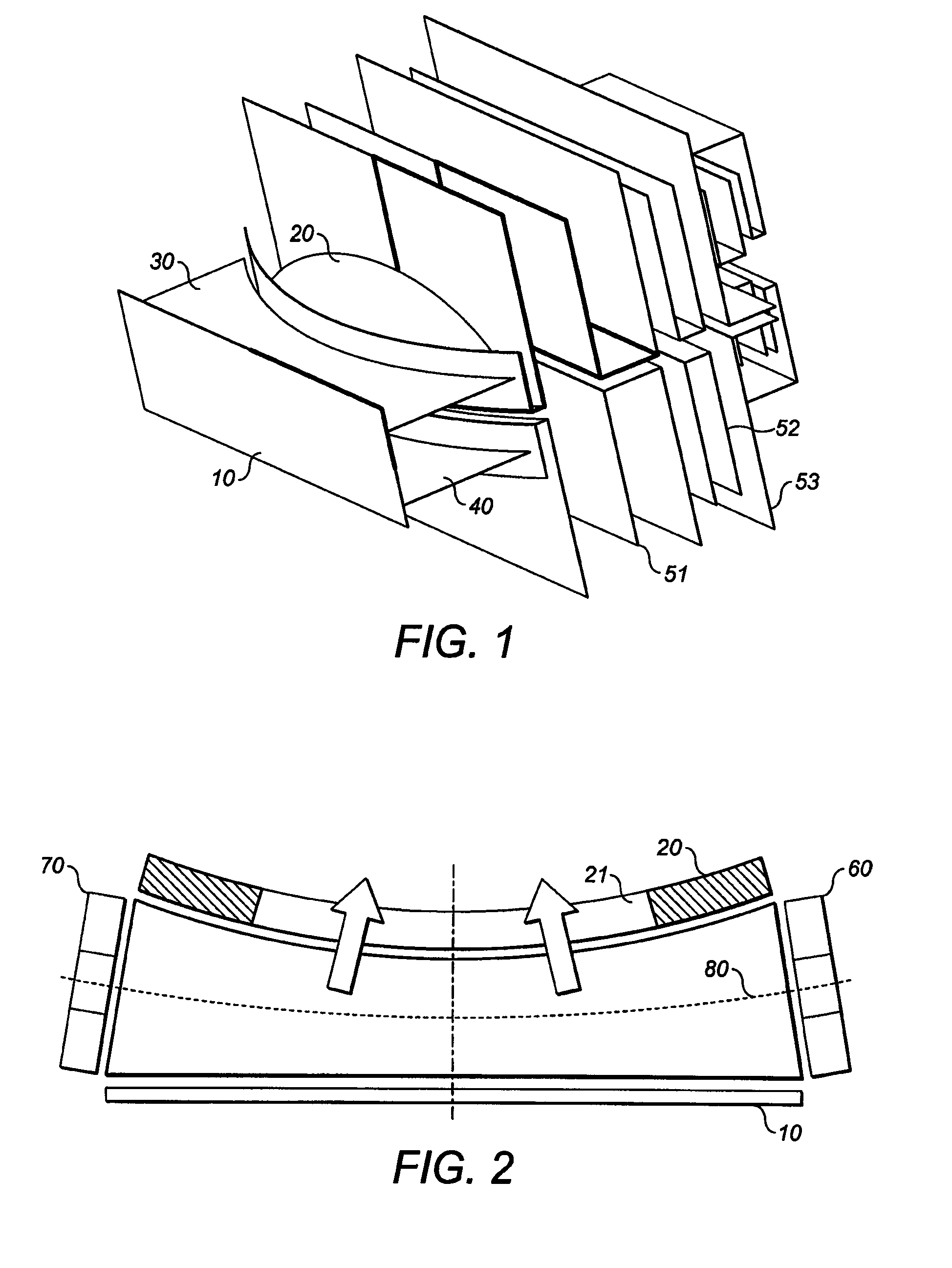
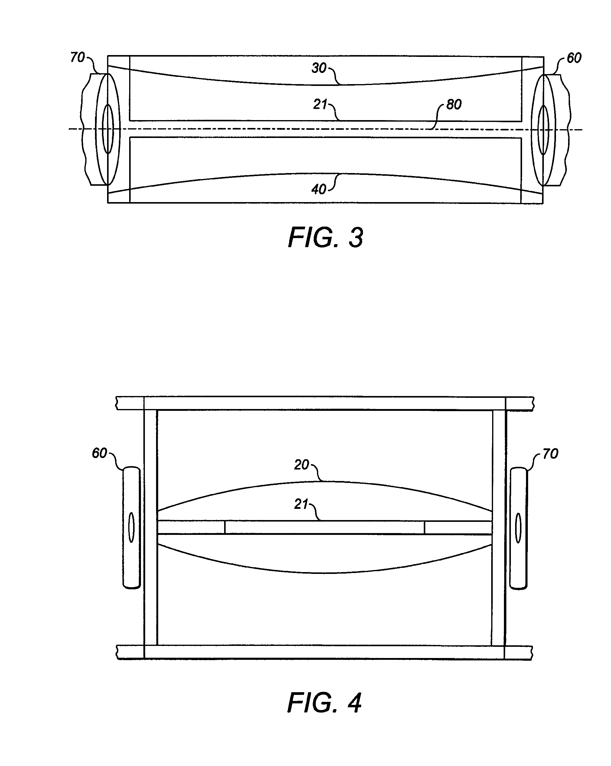
[0030]An ion storage trap in accordance with a preferred embodiment of the present invention will now be described with reference to the Figures. In contrast with previous devices having parallel or concentric surfaces of trap electrodes, it has been found to be both possible and advantageous to have surfaces with different curvatures Some examples are shown in FIGS. 1, 2 and 3.

[0031]The trap is formed from substantially elongate electrodes (unlike the 3D quadrupole ion trap). These electrodes have a different spacing from each other at both ends of the trap than they do in the central region of the trap—the ends of the electrodes are splayed out at the ends, or constrict at the ends. The number of electrodes can be 3 or more. Preferably an even number of electrodes is used. A four-electrode device is specifically described here, with splayed ends. The splaying of the ends of the electrodes can be seen in the Figures, most clearly in FIGS. 2 and 3, where electrodes 10 and 20 diverge...


PUM


Abstract

An ion trap comprises substantially elongate electrodes 10, 20 some of which are curved along their axis of elongation and which define a trapping volume between them. The sectional area of this trapping volume towards the extremities of the trap in the direction of elongation is different to the sectional area away from its extremities (eg towards the middle of the trap). In a preferred embodiment, the trap has a plurality of elongate electrodes, wherein opposed electrodes have different radii of curvature so that the trap splays towards its extremities. Thereby, a wider mass range of ions can be trapped and ejected, a higher space charge capacity (for a given trap length) is provided, and sharper ion beam focussing on ejection is possible.

Description

FIELD OF THE INVENTION[0001]This invention relates to an ion trap for storing and / or ejecting charged particles to a mass analyser. In particular, though not exclusively, the present invention relates to an ion trap suitable for injecting ions into an electrostatic trap such as a multi reflection time-of-flight analyser or an orbitrap.BACKGROUND OF THE INVENTION[0002]Ion traps, including RF ion traps, are well established devices that permit ion storage and ejection of stored ions into mass analyzers such as ion cyclotron resonance (ICR) analysers. Kofel, P.; Allemann, M.; Kellerhals, H. P. & Wanczek, K. P. External Trapped Ion Source for Ion Cyclotron Resonance Spectrometry, International Journal of Mass Spectrometry and Ion Processes, 1989, 87, 237-247 describe a rectangular trap in which all sides are held at the same potential, and the stray field from the ICR magnet produces the trapping action. Additionally the use of an ion accumulation RF-trap in or outside the magnetic fiel...

Claims


Application Information

Patent Timeline
Patent Type & Authority Patents(United States)
IPC IPC(8): H01J49/42H01J49/26
CPCH01J49/423H01J49/427H01J49/04H01J49/062H01J49/40
Inventor MAKAROV, ALEXANDERMONASTYRSKIY, MIKHAIL AGRINFELD, DMITRY E.
Owner THERMO FISHER SCI BREMEN
Why Eureka
Try Eureka