
Imaging system for cardiac planar imaging using a dedicated dual-head gamma camera

a planar imaging and imaging system technology, applied in the field of cardiac imaging, can solve the problems of not helping with the absorption issue, unable to achieve post-acquisition corrections in limited quantities, and poor sensitivity to detect heart abnormalities, and achieve the effect of reducing the large dead zon

Inactive Publication Date: 2011-09-13
JEFFERSON SCI ASSOCS LLC
View PDF9 Cites 2 Cited by
  • Summary
  • Abstract
  • Description
  • Claims
  • Application Information

AI Technical Summary

Benefits of technology

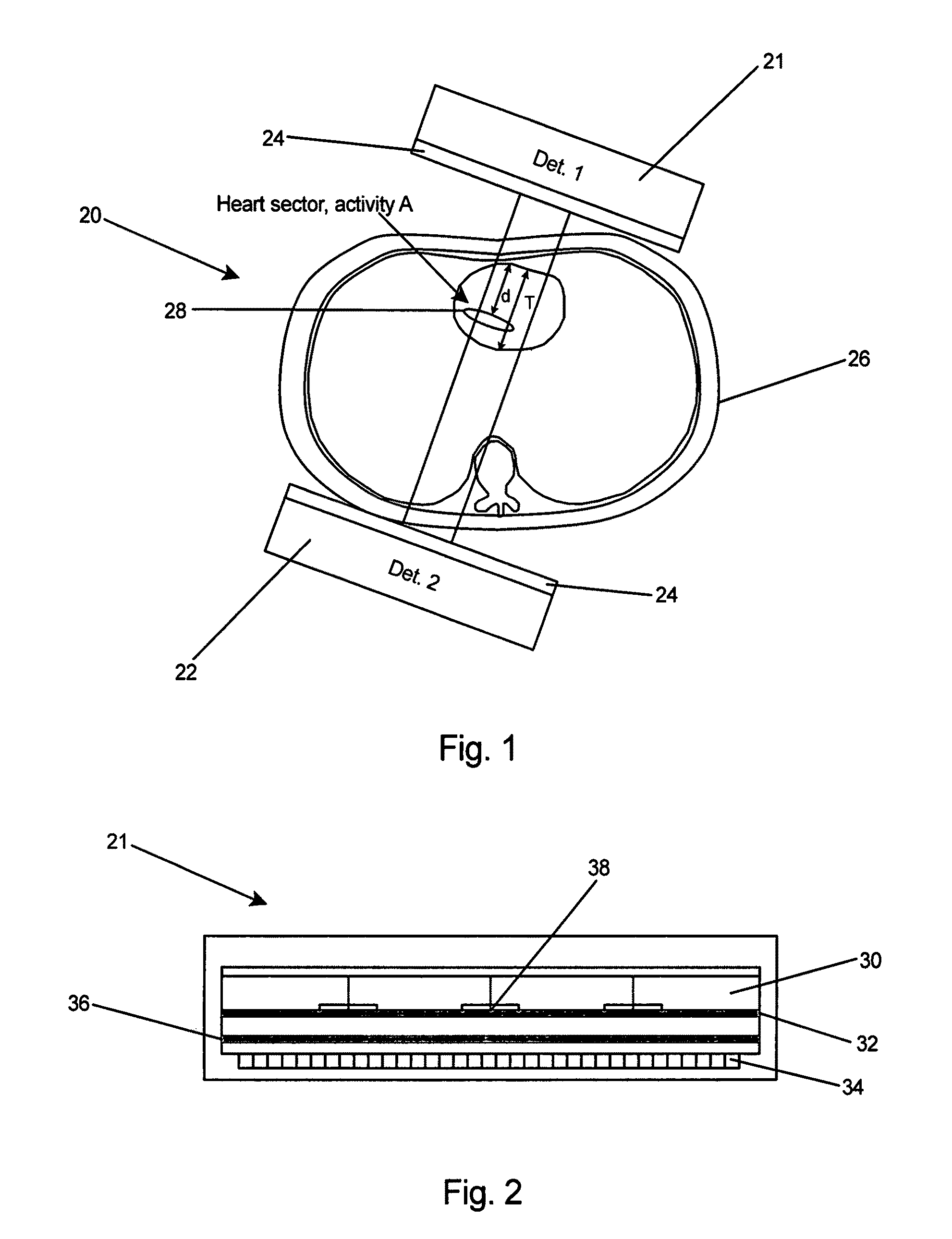
[0032](16) A significant reduction in the large dead zones between the individual PSPMTs in the array of photomultiplier tubes by implementation of optimized optical coupling involving a spreader window and reflective strips installed in the dead zones.
[0033]8) These and other objects and advantages of the present invention will be better understood by reading the following description along with reference to the drawings.

Problems solved by technology

Both types suffer from rather poor sensitivity to detect heart abnormalities located in the further part of the heart, away from the chest wall, hence far from the closest possible approach of the camera surface.
But this will not help with the absorption issue.
However, the situation is diametrically different during planar imaging, and especially during the dynamic first-pass procedure, when imaging is performed from only one pre-selected imaging direction (one view) and only limited post-acquisition corrections are possible.
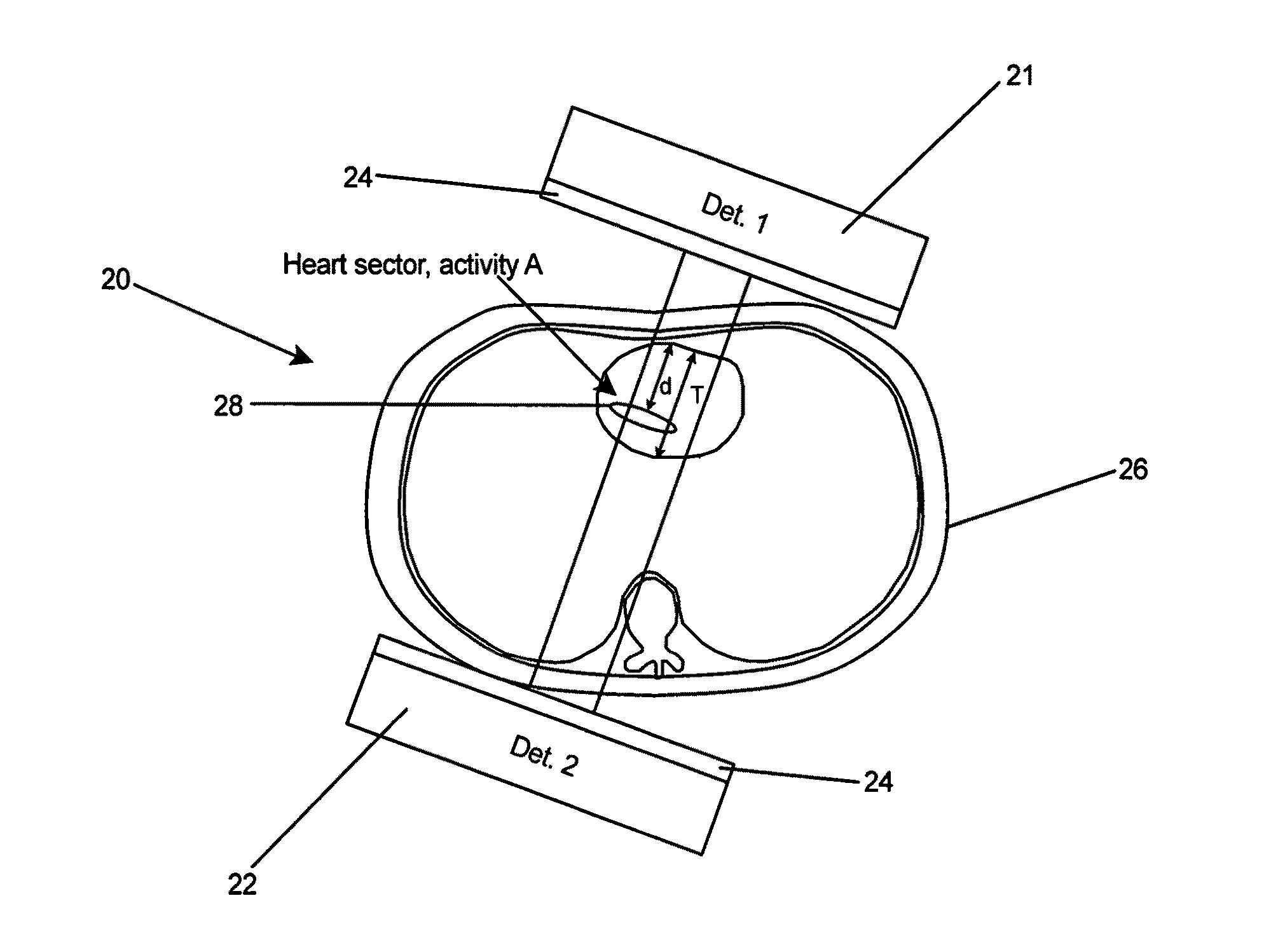
The major problem associated with the single-view planar (such as firstpass) cardiac imaging procedure is that the characteristic gamma radiation from Tc-99m undergoes substantial absorption when traversing tissues such as heart muscle tissue.
9) Alternative imaging labels with higher-energy gamma emissions undergoing lower absorption in the heart tissue, such as I-131 and In-113m, have been used in the past with success, but are not used in today's clinical environment, are not being manufactured in volume, and produce higher patient doses.

Method used


Image

  • Imaging system for cardiac planar imaging using a dedicated dual-head gamma camera
  • Imaging system for cardiac planar imaging using a dedicated dual-head gamma camera
  • Imaging system for cardiac planar imaging using a dedicated dual-head gamma camera

Examples


second embodiment

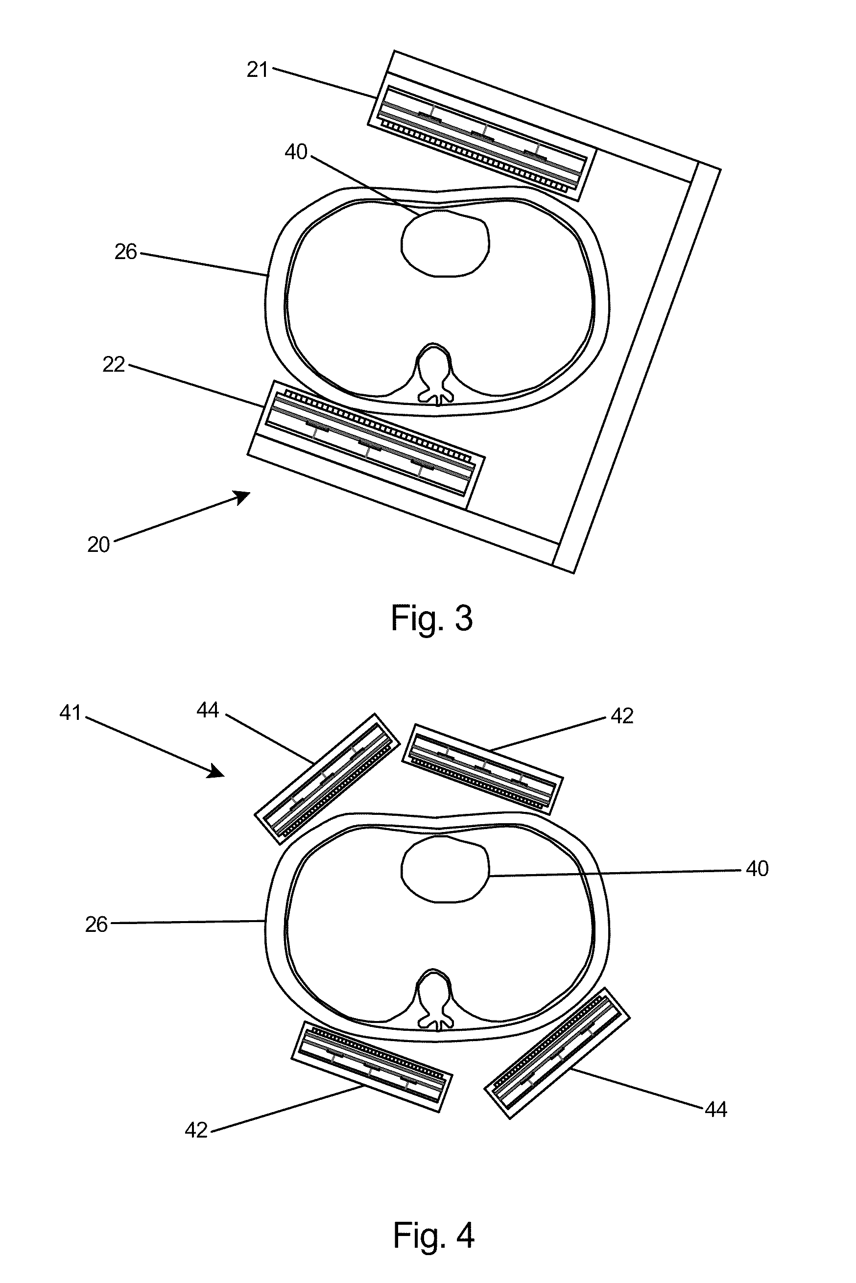
[0063]37) As shown in FIG. 4, the absorption-correcting first-pass cardiac system 41 of the present invention includes two pairs of co-registered gamma detector heads 42 and 44. The use of two pairs of compact co-registered gamma imagers provides a stereotactic view of the heart and region around the heart 40. The angles and positions of the detectors 42 and 44 relative to the patient's body and the relative angles between the two pairs are flexible and adjustable within the mechanical limitations dictated by the size of the detector heads and the associated mounting gear. The simultaneous dynamic recording of two stereotactic views of the heart will provide depths information to disentangle contributions from overlapping sections of the heart. Based on these complementary views, the specialized adjunct software will de-convolve these contributions based on a dynamic model of the propagation of the injection bolus in the heart chambers and in the coronary system. This will result in...

third embodiment

[0064]38) A possible third embodiment is to use the original one set of two co-registered cameras but to split the injection procedure into two injections separated by a short time of the order of about 60 seconds, with heart viewed from two different stereotactic directions. In this tightly executed timed procedure, after about 30 sec of data collection for the first view of the heart, the detector heads will be swiftly repositioned to the second view position and the new injection will be executed with a second imaging run of about 30 sec. The second injection will be adding the activity from a radioactive bolus to the activity present in the patient's body from the previous injection, but with proper modeling of the dynamic phenomena in the heart region and subsequent removal of background levels, more information about dynamics of the blood flow will be obtained than if limited to the one obtained from the first injection only. This approach enables the use of a more economical ...


PUM


Abstract

A cardiac imaging system employing dual gamma imaging heads co-registered with one another to provide two dynamic simultaneous views of the heart sector of a patient torso. A first gamma imaging head is positioned in a first orientation with respect to the heart sector and a second gamma imaging head is positioned in a second orientation with respect to the heart sector. An adjustment arrangement is capable of adjusting the distance between the separate imaging heads and the angle between the heads. With the angle between the imaging heads set to 180 degrees and operating in a range of 140-159 keV and at a rate of up to 500kHz, the imaging heads are co-registered to produce simultaneous dynamic recording of two stereotactic views of the heart. The use of co-registered imaging heads maximizes the uniformity of detection sensitivity of blood flow in and around the heart over the whole heart volume and minimizes radiation absorption effects. A normalization / image fusion technique is implemented pixel-by-corresponding pixel to increase signal for any cardiac region viewed in two images obtained from the two opposed detector heads for the same time bin. The imaging system is capable of producing enhanced first pass studies, bloodpool studies including planar, gated and non-gated EKG studies, planar EKG perfusion studies, and planar hot spot imaging.

Description

[0001]The United States of America may have certain rights to this invention under Management and Operating contract No. DE-ACO5-060R23177 from the Department of Energy.FIELD OF THE INVENTION[0002]1) This invention relates to cardiac imaging and more particularly to a cardiac imaging system using dual gamma imaging heads co-registered with one another to provide two dynamic simultaneous views of the heart region.BACKGROUND OF THE INVENTION[0003]2) Cardiac imaging and functional analysis is the largest single nuclear medical imaging application and represents the area of greatest unmet need in the current technology. Physicians require information on the anatomy and function of the heart in order to diagnose, prescribe treatment, and monitor results of intervention.[0004]3) First-Pass Radionuclide Angiography (RNA) provides the clinician with patient information for improved patient management that is either difficult and / or costly to obtain using other technologies. First-Pass RNA p...

Claims


Application Information

Patent Timeline
Patent Type & Authority Patents(United States)
IPC IPC(8): H01L27/146G01T1/20
CPCA61B6/00G01T1/1648A61B6/4233A61B6/4241A61B6/4258A61B6/4266A61B6/503A61B6/5205
Inventor MAJEWSKI, STANISLAWUMENO, MARC M.
Owner JEFFERSON SCI ASSOCS LLC
Learn More